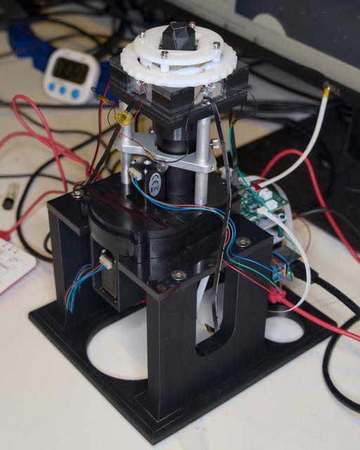
Meet the Transformer: 454 Bio’s One Pot sequencing instrument. At its core, the Transformer is an automated temperature controlled LED-TIRF microscope . Its main components are:
Temperature-controlled main body
High-power LEDs for excitation and photocleavage of Lightning Terminators™
Custom optics: automated focus adjustment and filter selection
Off-the-shelf camera sensor
Raspberry Pi computer with custom software and electronics to control and collect data
This section describes everything you will need to build your own sequencer.
1 - Hardware: Transformer Mark 3
Hardware Guide
Introduction
Our Sequencing instrument, “Transformer Mark 3.0”, is a custom-built total internal reflection fluorescence (TIRF) imaging system, specifically designed to support the innovative Lightning Terminators™ (LT) one pot sequencing. This system combines advanced optical engineering with the versatile control offered by a Raspberry Pi 4, augmented with stackable HAT (Hardware Attached on Top) boards for enhanced functionality.
Key functionalities
Temperature control and monitoring
The Transformer Mark 3.0 ensures optimal environmental conditions for sequencing reactions. Precision temperature control is crucial for accurate and reliable sequencing results.
Waveguide-based TIRF imaging module
At the heart of the system is the TIRF imaging module. Utilizing a waveguide approach, this module excites the fluorescent molecules linked to incorporated LTs a few hundreds of nanometers from the sequencing substrate surface. This module also performs effective UV cleavage of the terminating groups for continuous sequencing.
Motorized imaging filter switching and focus adjustment
To adapt to various imaging requirements, the Transformer Mark 3.0 includes a motorized filter wheel and focus adjustment mechanism. This allows for rapid and precise changes between different fluorescence channels and focus levels, ensuring sharp images and accurate data capture.
Procedure
The Transformer Mark 3.0 is assembled in four main sections. The process is detailed in the subpages below — we recommend assembling in this order (generally from bottom to top):
1.1 - Laboratory Stand
Laboratory Stand Guide
We use a simple laboratory stand that the Transformer is assembled on without skins or covers.
Tap the 3D printed base with M5 tap for the 4 flat head screws. Attach the adhesive-back bumpers to the underside of the base and attached the lab stand plate with 4 flat head screws. The assembled system is then attached to the lab stand with the two button head hex drive screws.
1.2 - Camera and focus
This section houses the core imaging components, including the high-resolution CMOS camera and the mechanisms for focus adjustment.
Start by attaching the Positioning Table (60935K71) with two M1.6 socket head screws (91292A264) and thin hex nuts (90710A145) to the camera mount. Then attach the focus motor mount to the other side of the positioning table with 4 zinc plated flat head screws (91263A862). Then mount the stepper motor (STEPPERONLINE Micro Step Motor Nema 8 Bipolar Stepper Motor 0.6A 5.7oz.in/4Ncm DIY Robot, stepperonline.com) with 4 flat head screws (92125A052). Attach the small pulley to the motor and the large pulley to the adjustment knob and tighten the pulley with one M2 socket head screw (91292A833).
Connect the two pulleys a 2x22 Buna-N O-ring (9262K183). Mount the camera (XSenIMX183) to the camera mount with 4 Socket Head Screws (91292A831). Set the subassembly aside.
1.3 - Filter wheel and optics
Situated above the camera assembly, this section contains the motorized filter wheel with optical tubing and an imaging lens, allowing for 4x magnification with seamless switching between different fluorescent channels.
Used to attach the filter housing bottom to the camera and focus assembly.
3x
316 Stainless Steel Hex Drive Flat Head Screw
93395A198
Used to attach the filter wheel hub to the filter wheel.
1x
Alloy Steel Cup-Point Set Screw
91390A092
Set screw to attach filter wheel assembly to stepper motor shaft.
4x
18-8 Stainless Steel Hex Drive Flat Head Screw
92125A052
Screws used to attach filter select stepper motor to the filter housing lid.
3x
Passivated 18-8 Stainless Steel Phillips Flat Head Screw
92010A424
Screws used to attach the aluminum legs to the filter housing lid.
3x
18-8 Stainless Steel Cup-Point Set Screw
92015A104
Set screws to fix the brace to the aluminum legs.
3x
Knurled-Head Thumb Screw
92545A119
Thumb screws to adjust the alignment of the optical stack.
3x
Button Head Hex Drive Screw
92095A185
Screws to hold together the filter wheel housing.
Start assembly by attaching the filter housing bottom to the camera and focus assembly with 6 flat head screws (92125A086). Place the assembly on the laboratory stand and attach the assembly with two button head hex drive screws (92095A212 – from laboratory stand hardware list).
Attach the filter wheel hub to the filter wheel with three hex drive flat head screws (93395A198) and insert a set screw to lock the filter wheel once ready to assemble (91390A092). Insert the filters into the wheel in the order shown below and set the complete filter wheel assembly aside.
Filter wheel order
Attach the stepper motor (STEPPERONLINE Micro Step Motor Nema 8 Bipolar Stepper Motor 0.6A 5.7oz.in/4Ncm DIY Robot, stepperonline.com) to the filter housing lid with 4 flat head screws (92125A052).
Optics (From top to bottom): Screw the 5x long working distance LM Plan achromatic objective lens (Bolioptics MT05073231) into a RMS to SM1 adapter (Thorlabs SM1A3), an adjustable lens tube (Thorlabs SM1V05), a stackable lens tube (Thorlabs SM1A10), and then finally into the filter housing lid.
Objective lens on adjustable optical tubes
Attach the three aluminum legs with three Phillips flat head screws (92010A424) to the filter housing lid and slide the alignment brace over the three legs and tighten the set screws (92015A104) to lock the brace in place. The thumb screws (92545A119) are adjusted to brace and align the optical stack.
Attach the fully assembled filter wheel to the shaft of the stepper motor and tighten the set screw. Carefully place the subassembly on the filter housing bottom ensuring that the filter wheel stop is not hitting the stop pin in the filter housing bottom. Secure the assembly with three button head screws (92095A185).
1.4 - TIRF LED and temperature control assemblies
Heat sink and LED mounting assemblies. These are installed into the main body.
Introduction
The TIRF LEDs and heaters are mounted directly to heat sinks, which do double duty: they both dissipate heat from the high-power LEDs and maintain a consistent temperature when the sequencing reservoir is inserted into the main body.
You will need to assemble four LED boards per unit:
1x each Edmund bandpass filters: 675/50nm (#86954), 625/50nm (#86953), 575/50nm (#86952), 525/50nm (#86951)
1x filter holder (3D printed, see CAD file)
1x Long working distance 5x LM Plan Achromatic Objective lens (BoliOptics, MT05073231)
1x SONY IMX183 CMOS camera (Vision Components)
1x Thorlabs Objective adapters (SM1A3)
1x Thorlabs 1” adjustable lens tubes (SM1V05)
1x Thorlabs 1” lens tubes (SM1L10)
LED
4x MK 3 Heatsinks (See CAD file)
2x visible LEDs boards (See pictures)
2x UV LED boards (See pictures)
1x each four color visible LEDs (LUXEON Rubix Color Line LEDs, MFG P/N: L1RX-L1RX-RED1000000000, L1RX-PCA1000000000, L1RX-GRN1000000000, L1RX-BLU1000000000)
16x UV LEDs (Light Avenue: LA UY20WP1)
4x 33Ohm UV LED current limit resistor (DigiKey: ERJ-P08J330V)
2x 1 Ohm 3/4W SMD 1206 visible LED current limit resistor (DigiKey: SR1206FR-7T1RL)
1x 1.27 Ohm 3/4W SMD 1206 visible LED current limit resistor (DigiKey: CRCW12061R27FKEAHP)
1x 1.8 Ohm 3/4W SMD 1206 visible LED current limit resistor (DigiKey: CRCW12061R80FKEAHP)
The LED Board Soldering picture shows the PCB for visible LEDs. First, clean the board and apply a thin layer of SAC305 solder paste (Mouser #910-SMD291SNL250T5). Using a stencil is recommended.
Place the LEDs (Red with PC Amber, Green with Blue) and the current limiting resistors (Red: 1.8 Ohm, PC Amber: 1.27 Ohm, Green: 1 Ohm, Blue: 1 Ohm) at the location shown below
Heat the board to 250-270C, the solder paste will melt and the LEDs and the resistors will be well attached. Use the tweezer to adjust the position if needed.
LED Board Soldering
The UV LEDs were connected in series (four as a set) by wire bonding.
Carefully solder the silicone tinned copper wires to the bottom of the PCB
LED Heatsink Preparation
Prepare a pea-sized volume of 8329TCM Thermally Conductive Adhesive by thoroughly mixing one half-pea-sized ball of 8329TCM-A and one half-pea-sized ball of 8329TCM-B. Spread a thin layer of the prepared 8329TCM over the Mk3 heatsinks, on the face that has the LED board seating area, in the region marked below. The layer should be roughly the thickness of a few pieces of paper
Attach an LED PCB to a heat sink
Place one of the visible LED boards (Either the Amber + Red board, or the Blue + Green board) onto the prepared surface. Make sure the board is well-aligned with the side fins and the center pin.
Press the stack together either by a press or by hand.
Repeat steps 1 through 8 for the rest of the visible and UV LED boards. It will take 24 hours for the 8329TCM to fully cure. Heating up to 40-50C can slightly speed up the curing process.
Heater Cable Assembly
Cut 2 lengths of 26 Gauge Enamel Wire roughly 50mm long. Strip one end of each wire segment, and solder the stripped end of each wire segment to one side of the underside of the 4.7 Ohm 16W 1% 2512 SMD Resistor
Prepare a pea-sized volume of 8329TCM Thermally Conductive Adhesive by thoroughly mixing one half-pea-sized ball of 8329TCM-A and one half-pea-sized ball of 8329TCM-B. Spread a thin layer of the prepared 8329TCM over one of the Mk3 heatsinks, on the face that does not have the center ribbon cable groove, in the region marked below. The layer should be roughly the thickness of a few pieces of paper
Place one of the prepared resistors, with the soldered face away from the heatsink, onto the bed of 8329TCM that was prepared. Press down on the resistor to ensure it is seated into the 8329TCM. It will take 24 hours for the 8329TCM to fully cure
Attach a heater to the heat sink
Repeat steps 10 through 12 for the remaining 3 Mk3 heatsink
Thermistor Cable Assembly
One thermistor is used per unit to monitor the temperature of one heatsink, which is used as a proxy for the temperature of the sample.
Prepare a pea-sized volume of 8329TCM Thermally Conductive Adhesive by thoroughly mixing one half-pea-sized ball of 8329TCM-A and one half-pea-sized ball of 8329TCM-B, and apply it to the thermistor.
Dip the thermistor and adhesive into the cylindrical hole of one of the heatsinks. Historically, we have used the red/amber heatsink for this, but there is no reason to use one heatsink over another. It will take 24 hours for the 8329TCM to fully cure
Splice female jumper cables to the other end of the thermistor cable.
1.5 - Main body
The topmost section forms the main body of the Transformer Mark 3.0. It integrates all the components into a cohesive unit, housing the sequencing reservoir, LED and heat sinks, heaters, temperature sensors, and providing structural integrity to the entire assembly.
Assembled main body with sequencing reservoir inserted
Please note that the pictured assembly is for illustration purposes only. It is from a previous iteration and is not fully representative of a correctly assembled heatsink.
4x Heat Sink Height Adjuster (Machined)
Reservoir insert plate
Quantity
Description
McMaster Part Number
Use
2x
18-8 Stainless Steel Narrow Cheese Head Slotted Screws
97710A113
Attaching the light shroud to the bottom of the main body.
2x
Super-Corrosion-Resistant 316 Stainless Steel Socket Head Screw
92290A320
Attach the main body to two of the aluminum legs of the assembly.
1x
Passivated 18-8 Stainless Steel Phillips Flat Head Screw
92010A424
Attach the main body to one of the aluminum legs of the assembly.
8x
Alloy Steel Socket Head Screw
91290A010
Attach the heat sink height adjusters to the main body.
8x
Stainless Steel Flat-Tip Set Screw
92605A024
Set screw to set the max height of the heat sink bearing.
4x
18-8 Stainless Steel Dowel Pin
91585A368
Dowel for heat sink bearing.
4x
Stainless Steel Ball Bearing
7804K124
Bearing setting maximum height of heat sink.
4x
18-8 Stainless Steel Hex Drive Flat Head Screw
92125A126
Attach the Reservoir Insert plate to the main body.
4x
18-8 Stainless Steel Shoulder Screw
90265A323
Shoulder screw used to attach Locking ring with standoffs to be attached to the Cam ring.
4x
Compression Spring
9657K604
Compression spring for shoulder screws.
Procedure
We start by attaching the light shroud (note the orientation of the shroud with respect to the three legs) to the main body using two narrow cheese head slotted screws (97710A113). We then attach the main body to the rest of the assembly via two socket head screws (92290A320) and one Phillips flat head screw (92010A424). Note: Carefully align the light shroud with the optical stack when positioning the main body on the assembly.
Attach the 4 heat sink height adjusters with 8 socket head screws (91290A010) to the main body. Start with the height adjusters placed in the middle of the extreme positions. The heat sink is raised by moving the adjuster closer towards the center of the main body and lowered by moving the adjuster further away from the center. When placing each of the 4 LED heat sink assemblies, gauge the alignment of the LEDs with the glass substrate in an assembled reservoir and adjust so that the LEDs are centered around the glass substrate. The assembly of the LED heat sinks is described here.
The next step is a little tricky. The cam ring needs to be placed onto the main body such that the heat sink pins are riding in the inner grove (see image below). If one of the pins rides in the outer grove the heat sink will not actuate properly.
Next we have to assemble the reservoir insert plate. Place one dowel pin (91585A368) in each of the 4 bearings (7804K124) and press them into the bottom slots of the reservoir insert plate.
Insert the 8 set screws (92605A024) halfway into the holes such that the bearings can freely move up and down in the space provided (see image below):
Once the Reservoir Insert plate has been attached to the main body using 4 flat head screws (92125A126) the set screws are adjusted until the pin from the heat sink no longer has “wiggle room”. Note that it is quite easy to overtighten the set screws so carefully adjust both screws in ¼ turn increments until the pin from the heat sink no longer moves freely.
Finally, the Locking Ring with standoffs is installed with 4 shoulder screws (90265A323) and 4 compression springs (9657K604). Turning the cam ring to the open position allows the insertion of a reservoir and once turned to the closed position pivots the LED heat sinks such that the pins set the distance of the LED to the edge of the substrate surface and locks the reservoir into position.
2 - Electronics
Electronics Guide
Introduction
The electronics of the 454 sequencer primarily live in custom Raspberry Pi HATs.
This guide assumes some basic electronics and soldering ability.
Base board
While prototyping an earlier revision, we developed a board that implements power delivery, the LED drivers, heater control, and some other (now-deprecated) features.
The full board layout and bill of materials suitable for having this board manufactured are available here.
We have been iterating on our hardware features since then. Since we have not formalized them into a new board design yet, instructions for assembly on prototyping boards are available here instead.
LED voltage selection
By default, the HAT’s LED connectors output 20V, which works well for the UV boards but will damage the visible light boards. To fix this, select 5V output on the LED N and S sections:
Depopulate (but hold on to) the 0 ohm resistors at R21, R25, R37, and R41.
Populate R22, R26, R38, and R42 using the 0 ohm resistors.
Camera trigger
The instrument software needs to be able to arbitrarily start and stop camera exposures at any time. We do this by outputting to the camera’s vertical sync or external trigger functionalities, which need to be wired into a GPIO pin on the Pi. The methods for doing this vary by camera:
Vision Components camera
For best results, we recommend the Vision Components IMX183 (grayscale, not the C version). This offers good image quality with the full field of view, potentially enabling tens of thousands of reads per slide.
Using the repeater board
The easiest way to access the external trigger is using their repeater board. Simply connect the trigger input to GPIO pin 6 on the Pi using a jumper cable.
By reworking your Pi
If you don’t have the repeater board, you can instead rework your Raspberry Pi to redirect the trigger input to GPIO pin 6.
This rework will permanently damage your Pi. It will no longer be able to use a standard Pi camera.
The following instructions are only for the Raspberry Pi 4 — the Pi 5 uses a different camera connector.
Locate pin 5 on the Pi’s camera connector. With standard Pi cameras, this pin is typically used to enable or disable the camera, but with the VC IMX183, it is the external trigger.
Using a scalpel or similar, carefully delaminate the copper trace under the pin to disconnect it from the CPU.
Solder a AWG 30 wire from pin 5 on the camera connector to GPIO pin 6, making sure that a HAT can still be inserted on top of the Pi.
Once either is completed, the camera module can be connected normally to the Pi per Vision Components’ instructions.
Pi HQ camera
A Pi HQ camera can achieve adequate results, though we recommend using a grayscale module — i.e. one whose Bayer filter has been removed. We do not recommend performing this removal on your own as it is very easy to accidentally damage the module. Instead, pre-modified modules can be purchased from several third parties.
External trigger is available using the XVS pad on the camera module. Solder wires to both the XVS and GND pads to be able to drive the signal.
XVS is at a 1.8v logic level, and the Pi’s GPIO pins are at a 3.3v logic level. While the base board has a level shifter built in, it is in the wrong direction. Instead, we use an off-the-shelf level shifter, like this one from SparkFun along with some resistors to create a voltage divider for the 1.8v reference voltage on the LV pin.
As pictured, the camera’s XVS and GND go to LV3 and a common GND. HV goes to one of the 3.3v pins on the Pi and HV3 goes to GPIO pin 3.
Once completed, the camera module can be connected normally the Pi.
Andor microscope camera
We have used a Andor Zyla camera during development. While it produces very good image quality, it has a narrow field of view and is not mechanically compatible with our current hardware. External trigger is accessible on a VGA/DE-15 connector (contact Andor support for pinout) and also requires a level shifter as this uses a 5v logic level.
This camera will need to connect to a Windows PC that has the Andor driver software installed and is on the same network as the Pi.
Stepper motor driver
We use stepper motors to rotate the filter wheel and adjust focus. To enable precise control, we opted to connect two sets of dual-channel H-bridges (Adafruit TB6612 breakout board for prototyping) directly to the Pi GPIOs. To make these connections cleaner, we mounted the H-bridges to a prototyping HAT.
While the two motors do end up using 10 GPIO pins total, the wiring is fairly straightforward:
TB6612 breakout
Pi GPIO: Focus
Pi GPIO: Filter
AIN1
GPIO 24
GPIO 7 (CE1)
AIN2
GPIO 25
GPIO 8 (CE0)
PWMA
GPIO 5
GPIO 12
BIN1
GPIO 26
GPIO 14 (TXD)
BIN2
GPIO 27
GPIO 15 (RXD)
PWMB
GPIO 5
GPIO 12
STBY
(disconnected)
(disconnected)
Vcc
3.3V
3.3V
Vm
5V
5V
GND
GND
GND
Note that GPIO 26 is not actually accessible using any of the through holes on the prototyping HAT. Instead, we have had to connect it directly to corresponding pin on the GPIO header.
The connectors to the motors are basic right angle jumper connectors. When wiring the motors, just make sure that MOT.A is connected to opposite sides of the same winding, etc.
Note that this powers the motors directly from the Pi’s 5V supply, and may draw as much as 1.5A. In our case, the I3A4W008A033V-001-R 5V buck converter provides more than enough power for the Pi and our peripherals.
Temperature control
We maintain the temperature of the slide using a temperature sensor and high-power resistors as heaters controlled using a PID loop.
Temperature sensor
Our software supports two types of temperature sensors to monitor slide temperature: a thermistor or a 1-wire sensor. One of the following temperature sensors should be mounted in the corresponding cutout in one of the heatsinks:
Thermistor and ADC
The thermistor-based temperature sensor is the easiest to maintain, as it does not require any hardware on the heatsink other than the thermistor itself. This greatly simplifies heatsink maintenance and replacement.
It does require a separate circuit to power the thermistor as part of a voltage divider and a ADC to read the value. For prototyping, we have been hand-soldering an Adafruit ADS1115 breakout board along with the appropriate resistors on a prototyping HAT:
The connections are fairly straightforward as well:
VDD to 3.3V
GND to GND
SCL to SCL with a pullup resistor to 3.3V
SDA to SDA with a pullup resistor to 3.3V
ADDR to GND for I2C address 0x48
A0 as the input from the thermistor through a voltage divider, described below
The connector to the thermistor itself is a basic right angle jumper connector. The orientation of the connection does not matter because thermistors, like all resistors, are non-polarized.
In our application, we replace the Arduino with the ADS1115 ADC. 3.3V is used as the reference voltage instead, and the voltage divider output through the thermistor goes to A0 on the ADC.
1-wire sensor
In the past, we have used a 1-wire sensor to measure the temperature. While this made it easy to implement software to read the output, it required some point-to-point microsoldering to power the sensor. This part would have to be remade if the heatsink that the sensor was mounted to needed to be replaced for any reason.
Heater wiring
The heater consists of resistors mounted directly to the heatsinks. These should be wired together in series and then connected to the output, which is currently on the same 6-pin FFC cable as the 1-wire sensor as shown above. If you are using the thermistor/ADC setup, simply leave the 1-wire sensor disconnected from the FFC cable and do not insert the FFC cable into the heatsink.
HAT feature bypasses
These features use GPIO pins that cannot simply be output to because of functionality on the base board. These will be need to be bypassed.
On the prototyping board for either the stepper drivers or the thermistor ADC, cut the pins corresponding to GPIO 5 and 6 such that the HAT above it will not be connected to them. This is demonstrated above in the stepper motor driver board.
3 - Instrument software
Microscope control software for automated data collection
Introduction
The instrument software is split into two main parts:
The HAL , which directly manages the hardware and collects images.
The UI , which coordinates data collection steps at a high level and allows use of the instrument as a manual microscope.
The HAL is written in C++ for performance and reliability and ease of integration with camera libraries, while the UI is written in Python with PySide (Qt) for ease of implementation. The two communicate over the network using a JSON API, making it possible to remotely manage a transformer.
This guide assumes general knowledge of Linux systems and the Raspberry Pi.
Setup
We will soon make a prebuilt Raspberry Pi image that can be flashed directly to a SD card and used immediately. Until then, or for development purposes, the steps below describe how to set one up from scratch.
Installation
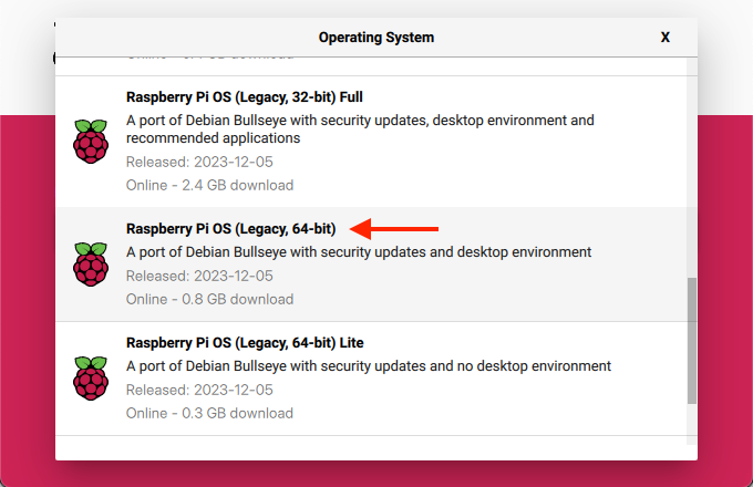
Base operating system image
The HAL requires Raspbian Bullseye 64-bit (i.e. it has not been tested with Buster). This can be installed using the Raspberry Pi Imager as described on the Raspberry Pi website. As of this writing, this OS is a little buried: after opening the “Operating System” menu, open “Raspberry Pi OS (other)” and scroll down to “Raspberry Pi OS (Legacy, 64-bit)”.
We recommend setting up the Pi with only basic peripherals (mouse, keyboard, monitor, and optionally wired network) connected — do not plug in any 454 hardware yet.
Common dependencies
There are a number of packages that will need to be installed to be able to compile and run the UI and HAL. Turn on the Pi, connect it to a network, and in a terminal, run the following:
# Initial setupsudo apt update
sudo apt upgrade
# Convenience packagessudo apt install htop tmux mosh git build-essential rsync python3-pip
# Needed to build libcamera-appssudo apt install -y libepoxy-dev libjpeg-dev libtiff5-dev
sudo apt install -y qtbase5-dev libqt5core5a libqt5gui5 libqt5widgets5
sudo apt install -y libavcodec-dev libavdevice-dev libavformat-dev libswresample-dev
sudo apt install -y cmake libboost-program-options-dev libdrm-dev libexif-dev
sudo apt install -y libboost-dev
sudo apt install -y libgnutls28-dev openssl libtiff5-dev
sudo apt install -y qtbase5-dev libqt5core5a libqt5gui5 libqt5widgets5
sudo apt install -y meson
sudo apt install -y libglib2.0-dev libgstreamer-plugins-base1.0-dev
sudo apt install -y libpng-dev
sudo pip3 install jinja2
sudo pip3 install pyyaml ply
sudo pip3 install --upgrade meson
# Pi-specific packages for hardware access# These *can* be installed on a regular aarch64 Debian Bullseye installation# to compile there instead, but they will have to be manually copied from the Pi reposudo apt install libcamera-dev libcamera0 libpigpio1 libpigpio-dev raspberrypi-kernel
# Python packages for UIsudo apt install python3-pyside2.* python3-pil python3-numpy python3-jsonschema
454 software
Now, it’s time to install the 454 software:
# Create required directoriesmkdir -p ~/454/output/manual
sudo mkdir -p /454/hal
# Clone, compile, and install the HALgit clone https://github.com/454bio/tirf-hal.git ~/454/hal-src
cd ~/454/hal-src
git submodule update --init --recursive
meson setup builddir
cd builddir
meson compile
rsync -avd ./ /454/hal/
# Clone the UIgit clone https://github.com/454bio/tirf-ui.git ~/454/ui
Configuration
To configure your specific hardware, first start by copying over the default configuration files:
The i2c_ variables here are consistent with the circuit described in the Electronics section, and the thermistor parameters are consistent with the recommended thermistor. If you selected a different thermistor, the appropriate values can be obtained from the datasheet.
If you are using the thermistor, your config must not also contain the 1-wire section below.
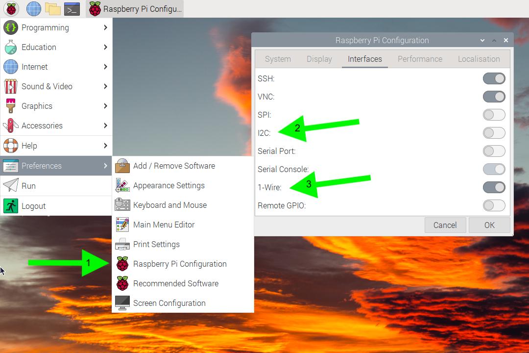
1-wire
First, you’ll need to enable the 1-Wire interface. In the “Interfaces” tab, turn on 1-Wire (labeled 3 above), then press OK. You will be prompted to reboot your Pi.
Then, edit /454/hardware_configuration_transformer.json to include the following:
If you are using the the 1-wire sensor, your config must not also contain the thermistor section above.
Camera
Vision Components camera
First, set up your Pi according to the Vision Components documentation.
After rebooting, it may be useful to proceed with normal setup first just to validate that the camera is working. To integrate with our software, set up external trigger in their driver software by editing /boot/config_vc-mipi-driver-bcm2835.txt:
Choose the config_vc-mipi-driver-bcm2835-raspi4B.txt platform
Choose the dtoverlay=vc-mipi-bcm2835-raspi3Bplus-cam0-imx183 overlay
Set the dtparam=cam0_sensor_mode_5 parameter
Leave the dtparam=cam0_io_config=8 parameter alone
Reboot
The VC camera has a quirk where it will use the external trigger to set the duration of the pulses only if the exposure time is 10 ms or less. At longer exposures, it will expose for the set duration and ignore the second pulse.
This is set in the HAL’s camera configuration at /454/vc_camera_config.json:
"exposure_time_us":10000,
Pi HQ camera
Support for the Pi HQ camera is included out of the box with Raspbian. To enable external trigger, append imx477.trigger_mode=2 to your /boot/cmdline.txt.
On a typical transformer, a complete /boot/cmdline.txt contains the following:
If you are using a standard color camera module (and not a debayered grayscale module), edit the HAL configuration at /454/libcamera_config.json to read:
"sensor_type":"imx477",
Filter wheel
The HAL configuration at /454/hardware_configuration_transformer.json has reasonable defaults for filter wheel position:
If images are out of focus between wavelengths, the positions may be adjusted:
Edit the configuration such that all of the positions are at zero (i.e. "red": 0, "orange": 0, ...).
Close the UI and restart the HAL (see below).
Use the live preview to image each wavelength and focus using the manual focus adjustment buttons. Take note of the values reported in the status bar (“Filter at [color name] position ([step number])”).
Add a desktop shortcut to the UI by copying 454-sequencing.desktop to ~/Desktop/454-sequencing.desktop
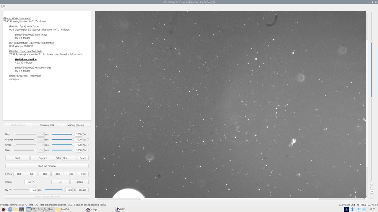
Usage
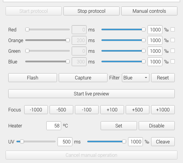
Manual image capture
The manual controls allow realtime control of the sequencer hardware. To use the manual controls, open the UI and click the “Manual controls” button.
The top half configures visible light TIRF. After enabling any number of LEDs using the checkbox on the right, an exposure time in ms and intensity in ‰ (parts per 1000) can be set. These TIRF settings will be used when any of the following buttons are pushed:
“Flash”, which flashes the LEDs without capturing an image
“Capture”, which captures one image, saves it in ~/454/output/manual, and displays it in the preview
“Start live preview”, which continuously captures images and displays them in the preview.
The HAL automatically exposes the sensor just long enough for the configured TIRF.
If the filter is anything other than “Any filter”, the filter wheel will be moved to the set position before an image is captured.
The focus buttons nudge the base focus — the focus for all other colors will be adjusted by the same amount.
The “Heater” section will only be present if a temperature sensor is configured. The “Set” and “Disable” buttons respectively set the specified temperature or disable the heater entirely.
The “UV” section allows manual cleaving with the “Cleave”, and the time and intensity behave exactly like the visible light controls.
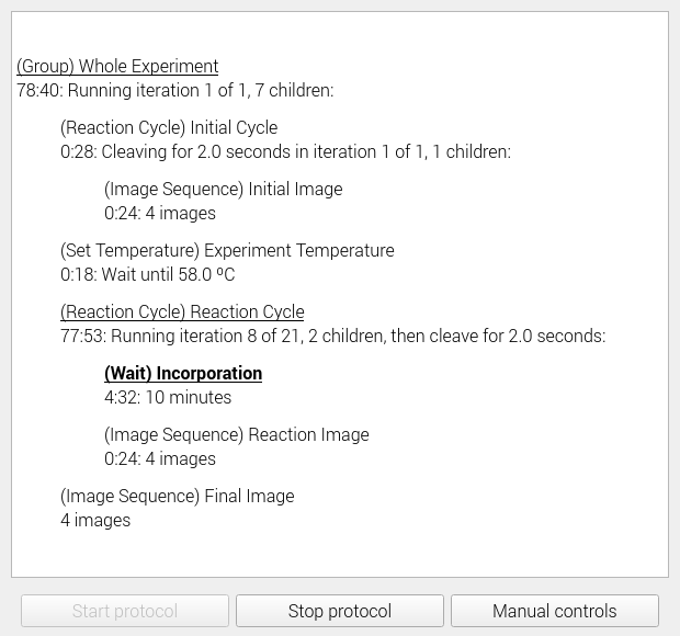
Automated data collection
To collect data for sequencing automatically, open one of the preset sequencing protocols from the “File –> Open” dialog and then start it by pressing “Start protocol”. It will run until completion unless stopped with the “Stop protocol” button or a hardware error is detected.
If you would like to write your own automated sequencing protocol, you will have to do so manually as we have not yet implemented a protocol editor. Sequencing protocols are written in JSON, and can be validated with their JSON Schema specification .
Legacy code
The HAL used to be a fork of rpicam-apps (back when it was called libcamera-apps). This version of the code, along with all of its history, is available here .
A previous version of the instrument software was written in pure Python with GTK. While it only supports basic TIRF with the Pi camera (i.e. it lacks support for direct exposure control, the filter wheel, focus control, and live preview), it is available here for historical purposes only.