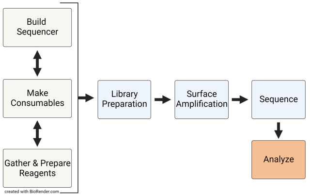
We’ve assembled everything needed to build your very own LED-TIRF Transformer, make sequencing consumables, prepare a DNA library, and sequence that library on your Transformer in this Documentation page.
Begin by navigating through the Build and Make Consumables documentation. Here you will find CAD and parts lists to build your Transformer, materials and reagents to make sequencing reaction buffer, protocols for preparing sequencing substrates, and much more. Once the hardware, electronics, and instrument software are complete, you can begin testing your system by simply imaging a prepared sequencing reservoir.
The real excitement starts when you get to sequence a DNA library. We’ve provided the backbone of your library molecule so you can easily order a pool of diverse DNA templates to sequence and assess the performance of your Transformer. Follow the protocols outlined in the Sequencing documentation to get started.
Once sequencing is complete, proceed to the Analyze documentation to transform your raw images into quality scored, de-phased DNA sequence aligned to your reference sequence.
Navigating 454 Bio Open Source Content
1 - Build your sequencer
Build your sequencer
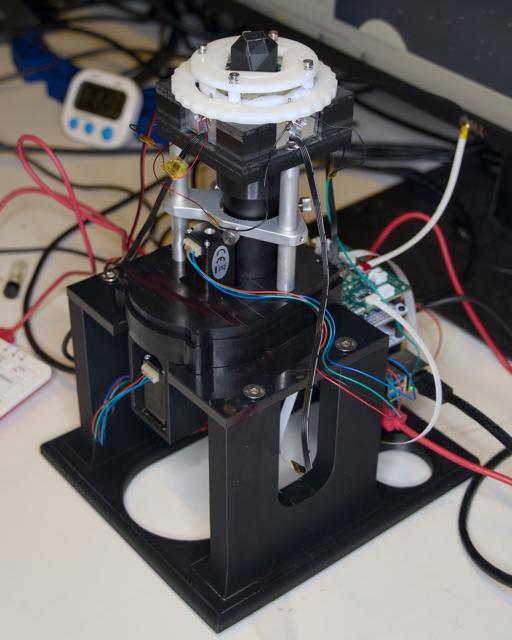
Meet the Transformer: 454 Bio’s One Pot sequencing instrument. At its core, the Transformer is an automated temperature controlled LED-TIRF microscope . Its main components are:
Temperature-controlled main body
High-power LEDs for excitation and photocleavage of Lightning Terminators™
Custom optics: automated focus adjustment and filter selection
Off-the-shelf camera sensor
Raspberry Pi computer with custom software and electronics to control and collect data
This section describes everything you will need to build your own sequencer.
1.1 - Hardware: Transformer Mark 3
Hardware Guide
Introduction
Our Sequencing instrument, “Transformer Mark 3.0”, is a custom-built total internal reflection fluorescence (TIRF) imaging system, specifically designed to support the innovative Lightning Terminators™ (LT) one pot sequencing. This system combines advanced optical engineering with the versatile control offered by a Raspberry Pi 4, augmented with stackable HAT (Hardware Attached on Top) boards for enhanced functionality.
Key functionalities
Temperature control and monitoring
The Transformer Mark 3.0 ensures optimal environmental conditions for sequencing reactions. Precision temperature control is crucial for accurate and reliable sequencing results.
Waveguide-based TIRF imaging module
At the heart of the system is the TIRF imaging module. Utilizing a waveguide approach, this module excites the fluorescent molecules linked to incorporated LTs a few hundreds of nanometers from the sequencing substrate surface. This module also performs effective UV cleavage of the terminating groups for continuous sequencing.
Motorized imaging filter switching and focus adjustment
To adapt to various imaging requirements, the Transformer Mark 3.0 includes a motorized filter wheel and focus adjustment mechanism. This allows for rapid and precise changes between different fluorescence channels and focus levels, ensuring sharp images and accurate data capture.
Procedure
The Transformer Mark 3.0 is assembled in four main sections. The process is detailed in the subpages below — we recommend assembling in this order (generally from bottom to top):
1.1.1 - Laboratory Stand
Laboratory Stand Guide
We use a simple laboratory stand that the Transformer is assembled on without skins or covers.
Tap the 3D printed base with M5 tap for the 4 flat head screws. Attach the adhesive-back bumpers to the underside of the base and attached the lab stand plate with 4 flat head screws. The assembled system is then attached to the lab stand with the two button head hex drive screws.
1.1.2 - Camera and focus
This section houses the core imaging components, including the high-resolution CMOS camera and the mechanisms for focus adjustment.
Start by attaching the Positioning Table (60935K71) with two M1.6 socket head screws (91292A264) and thin hex nuts (90710A145) to the camera mount. Then attach the focus motor mount to the other side of the positioning table with 4 zinc plated flat head screws (91263A862). Then mount the stepper motor (STEPPERONLINE Micro Step Motor Nema 8 Bipolar Stepper Motor 0.6A 5.7oz.in/4Ncm DIY Robot, stepperonline.com) with 4 flat head screws (92125A052). Attach the small pulley to the motor and the large pulley to the adjustment knob and tighten the pulley with one M2 socket head screw (91292A833).
Connect the two pulleys a 2x22 Buna-N O-ring (9262K183). Mount the camera (XSenIMX183) to the camera mount with 4 Socket Head Screws (91292A831). Set the subassembly aside.
1.1.3 - Filter wheel and optics
Situated above the camera assembly, this section contains the motorized filter wheel with optical tubing and an imaging lens, allowing for 4x magnification with seamless switching between different fluorescent channels.
Used to attach the filter housing bottom to the camera and focus assembly.
3x
316 Stainless Steel Hex Drive Flat Head Screw
93395A198
Used to attach the filter wheel hub to the filter wheel.
1x
Alloy Steel Cup-Point Set Screw
91390A092
Set screw to attach filter wheel assembly to stepper motor shaft.
4x
18-8 Stainless Steel Hex Drive Flat Head Screw
92125A052
Screws used to attach filter select stepper motor to the filter housing lid.
3x
Passivated 18-8 Stainless Steel Phillips Flat Head Screw
92010A424
Screws used to attach the aluminum legs to the filter housing lid.
3x
18-8 Stainless Steel Cup-Point Set Screw
92015A104
Set screws to fix the brace to the aluminum legs.
3x
Knurled-Head Thumb Screw
92545A119
Thumb screws to adjust the alignment of the optical stack.
3x
Button Head Hex Drive Screw
92095A185
Screws to hold together the filter wheel housing.
Start assembly by attaching the filter housing bottom to the camera and focus assembly with 6 flat head screws (92125A086). Place the assembly on the laboratory stand and attach the assembly with two button head hex drive screws (92095A212 – from laboratory stand hardware list).
Attach the filter wheel hub to the filter wheel with three hex drive flat head screws (93395A198) and insert a set screw to lock the filter wheel once ready to assemble (91390A092). Insert the filters into the wheel in the order shown below and set the complete filter wheel assembly aside.
Filter wheel order
Attach the stepper motor (STEPPERONLINE Micro Step Motor Nema 8 Bipolar Stepper Motor 0.6A 5.7oz.in/4Ncm DIY Robot, stepperonline.com) to the filter housing lid with 4 flat head screws (92125A052).
Optics (From top to bottom): Screw the 5x long working distance LM Plan achromatic objective lens (Bolioptics MT05073231) into a RMS to SM1 adapter (Thorlabs SM1A3), an adjustable lens tube (Thorlabs SM1V05), a stackable lens tube (Thorlabs SM1A10), and then finally into the filter housing lid.
Objective lens on adjustable optical tubes
Attach the three aluminum legs with three Phillips flat head screws (92010A424) to the filter housing lid and slide the alignment brace over the three legs and tighten the set screws (92015A104) to lock the brace in place. The thumb screws (92545A119) are adjusted to brace and align the optical stack.
Attach the fully assembled filter wheel to the shaft of the stepper motor and tighten the set screw. Carefully place the subassembly on the filter housing bottom ensuring that the filter wheel stop is not hitting the stop pin in the filter housing bottom. Secure the assembly with three button head screws (92095A185).
1.1.4 - TIRF LED and temperature control assemblies
Heat sink and LED mounting assemblies. These are installed into the main body.
Introduction
The TIRF LEDs and heaters are mounted directly to heat sinks, which do double duty: they both dissipate heat from the high-power LEDs and maintain a consistent temperature when the sequencing reservoir is inserted into the main body.
You will need to assemble four LED boards per unit:
1x each Edmund bandpass filters: 675/50nm (#86954), 625/50nm (#86953), 575/50nm (#86952), 525/50nm (#86951)
1x filter holder (3D printed, see CAD file)
1x Long working distance 5x LM Plan Achromatic Objective lens (BoliOptics, MT05073231)
1x SONY IMX183 CMOS camera (Vision Components)
1x Thorlabs Objective adapters (SM1A3)
1x Thorlabs 1” adjustable lens tubes (SM1V05)
1x Thorlabs 1” lens tubes (SM1L10)
LED
4x MK 3 Heatsinks (See CAD file)
2x visible LEDs boards (See pictures)
2x UV LED boards (See pictures)
1x each four color visible LEDs (LUXEON Rubix Color Line LEDs, MFG P/N: L1RX-L1RX-RED1000000000, L1RX-PCA1000000000, L1RX-GRN1000000000, L1RX-BLU1000000000)
16x UV LEDs (Light Avenue: LA UY20WP1)
4x 33Ohm UV LED current limit resistor (DigiKey: ERJ-P08J330V)
2x 1 Ohm 3/4W SMD 1206 visible LED current limit resistor (DigiKey: SR1206FR-7T1RL)
1x 1.27 Ohm 3/4W SMD 1206 visible LED current limit resistor (DigiKey: CRCW12061R27FKEAHP)
1x 1.8 Ohm 3/4W SMD 1206 visible LED current limit resistor (DigiKey: CRCW12061R80FKEAHP)
The LED Board Soldering picture shows the PCB for visible LEDs. First, clean the board and apply a thin layer of SAC305 solder paste (Mouser #910-SMD291SNL250T5). Using a stencil is recommended.
Place the LEDs (Red with PC Amber, Green with Blue) and the current limiting resistors (Red: 1.8 Ohm, PC Amber: 1.27 Ohm, Green: 1 Ohm, Blue: 1 Ohm) at the location shown below
Heat the board to 250-270C, the solder paste will melt and the LEDs and the resistors will be well attached. Use the tweezer to adjust the position if needed.
LED Board Soldering
The UV LEDs were connected in series (four as a set) by wire bonding.
Carefully solder the silicone tinned copper wires to the bottom of the PCB
LED Heatsink Preparation
Prepare a pea-sized volume of 8329TCM Thermally Conductive Adhesive by thoroughly mixing one half-pea-sized ball of 8329TCM-A and one half-pea-sized ball of 8329TCM-B. Spread a thin layer of the prepared 8329TCM over the Mk3 heatsinks, on the face that has the LED board seating area, in the region marked below. The layer should be roughly the thickness of a few pieces of paper
Attach an LED PCB to a heat sink
Place one of the visible LED boards (Either the Amber + Red board, or the Blue + Green board) onto the prepared surface. Make sure the board is well-aligned with the side fins and the center pin.
Press the stack together either by a press or by hand.
Repeat steps 1 through 8 for the rest of the visible and UV LED boards. It will take 24 hours for the 8329TCM to fully cure. Heating up to 40-50C can slightly speed up the curing process.
Heater Cable Assembly
Cut 2 lengths of 26 Gauge Enamel Wire roughly 50mm long. Strip one end of each wire segment, and solder the stripped end of each wire segment to one side of the underside of the 4.7 Ohm 16W 1% 2512 SMD Resistor
Prepare a pea-sized volume of 8329TCM Thermally Conductive Adhesive by thoroughly mixing one half-pea-sized ball of 8329TCM-A and one half-pea-sized ball of 8329TCM-B. Spread a thin layer of the prepared 8329TCM over one of the Mk3 heatsinks, on the face that does not have the center ribbon cable groove, in the region marked below. The layer should be roughly the thickness of a few pieces of paper
Place one of the prepared resistors, with the soldered face away from the heatsink, onto the bed of 8329TCM that was prepared. Press down on the resistor to ensure it is seated into the 8329TCM. It will take 24 hours for the 8329TCM to fully cure
Attach a heater to the heat sink
Repeat steps 10 through 12 for the remaining 3 Mk3 heatsink
Thermistor Cable Assembly
One thermistor is used per unit to monitor the temperature of one heatsink, which is used as a proxy for the temperature of the sample.
Prepare a pea-sized volume of 8329TCM Thermally Conductive Adhesive by thoroughly mixing one half-pea-sized ball of 8329TCM-A and one half-pea-sized ball of 8329TCM-B, and apply it to the thermistor.
Dip the thermistor and adhesive into the cylindrical hole of one of the heatsinks. Historically, we have used the red/amber heatsink for this, but there is no reason to use one heatsink over another. It will take 24 hours for the 8329TCM to fully cure
Splice female jumper cables to the other end of the thermistor cable.
1.1.5 - Main body
The topmost section forms the main body of the Transformer Mark 3.0. It integrates all the components into a cohesive unit, housing the sequencing reservoir, LED and heat sinks, heaters, temperature sensors, and providing structural integrity to the entire assembly.
Assembled main body with sequencing reservoir inserted
Please note that the pictured assembly is for illustration purposes only. It is from a previous iteration and is not fully representative of a correctly assembled heatsink.
4x Heat Sink Height Adjuster (Machined)
Reservoir insert plate
Quantity
Description
McMaster Part Number
Use
2x
18-8 Stainless Steel Narrow Cheese Head Slotted Screws
97710A113
Attaching the light shroud to the bottom of the main body.
2x
Super-Corrosion-Resistant 316 Stainless Steel Socket Head Screw
92290A320
Attach the main body to two of the aluminum legs of the assembly.
1x
Passivated 18-8 Stainless Steel Phillips Flat Head Screw
92010A424
Attach the main body to one of the aluminum legs of the assembly.
8x
Alloy Steel Socket Head Screw
91290A010
Attach the heat sink height adjusters to the main body.
8x
Stainless Steel Flat-Tip Set Screw
92605A024
Set screw to set the max height of the heat sink bearing.
4x
18-8 Stainless Steel Dowel Pin
91585A368
Dowel for heat sink bearing.
4x
Stainless Steel Ball Bearing
7804K124
Bearing setting maximum height of heat sink.
4x
18-8 Stainless Steel Hex Drive Flat Head Screw
92125A126
Attach the Reservoir Insert plate to the main body.
4x
18-8 Stainless Steel Shoulder Screw
90265A323
Shoulder screw used to attach Locking ring with standoffs to be attached to the Cam ring.
4x
Compression Spring
9657K604
Compression spring for shoulder screws.
Procedure
We start by attaching the light shroud (note the orientation of the shroud with respect to the three legs) to the main body using two narrow cheese head slotted screws (97710A113). We then attach the main body to the rest of the assembly via two socket head screws (92290A320) and one Phillips flat head screw (92010A424). Note: Carefully align the light shroud with the optical stack when positioning the main body on the assembly.
Attach the 4 heat sink height adjusters with 8 socket head screws (91290A010) to the main body. Start with the height adjusters placed in the middle of the extreme positions. The heat sink is raised by moving the adjuster closer towards the center of the main body and lowered by moving the adjuster further away from the center. When placing each of the 4 LED heat sink assemblies, gauge the alignment of the LEDs with the glass substrate in an assembled reservoir and adjust so that the LEDs are centered around the glass substrate. The assembly of the LED heat sinks is described here.
The next step is a little tricky. The cam ring needs to be placed onto the main body such that the heat sink pins are riding in the inner grove (see image below). If one of the pins rides in the outer grove the heat sink will not actuate properly.
Next we have to assemble the reservoir insert plate. Place one dowel pin (91585A368) in each of the 4 bearings (7804K124) and press them into the bottom slots of the reservoir insert plate.
Insert the 8 set screws (92605A024) halfway into the holes such that the bearings can freely move up and down in the space provided (see image below):
Once the Reservoir Insert plate has been attached to the main body using 4 flat head screws (92125A126) the set screws are adjusted until the pin from the heat sink no longer has “wiggle room”. Note that it is quite easy to overtighten the set screws so carefully adjust both screws in ¼ turn increments until the pin from the heat sink no longer moves freely.
Finally, the Locking Ring with standoffs is installed with 4 shoulder screws (90265A323) and 4 compression springs (9657K604). Turning the cam ring to the open position allows the insertion of a reservoir and once turned to the closed position pivots the LED heat sinks such that the pins set the distance of the LED to the edge of the substrate surface and locks the reservoir into position.
1.2 - Electronics
Electronics Guide
Introduction
The electronics of the 454 sequencer primarily live in custom Raspberry Pi HATs.
This guide assumes some basic electronics and soldering ability.
Base board
While prototyping an earlier revision, we developed a board that implements power delivery, the LED drivers, heater control, and some other (now-deprecated) features.
The full board layout and bill of materials suitable for having this board manufactured are available here.
We have been iterating on our hardware features since then. Since we have not formalized them into a new board design yet, instructions for assembly on prototyping boards are available here instead.
LED voltage selection
By default, the HAT’s LED connectors output 20V, which works well for the UV boards but will damage the visible light boards. To fix this, select 5V output on the LED N and S sections:
Depopulate (but hold on to) the 0 ohm resistors at R21, R25, R37, and R41.
Populate R22, R26, R38, and R42 using the 0 ohm resistors.
Camera trigger
The instrument software needs to be able to arbitrarily start and stop camera exposures at any time. We do this by outputting to the camera’s vertical sync or external trigger functionalities, which need to be wired into a GPIO pin on the Pi. The methods for doing this vary by camera:
Vision Components camera
For best results, we recommend the Vision Components IMX183 (grayscale, not the C version). This offers good image quality with the full field of view, potentially enabling tens of thousands of reads per slide.
Using the repeater board
The easiest way to access the external trigger is using their repeater board. Simply connect the trigger input to GPIO pin 6 on the Pi using a jumper cable.
By reworking your Pi
If you don’t have the repeater board, you can instead rework your Raspberry Pi to redirect the trigger input to GPIO pin 6.
This rework will permanently damage your Pi. It will no longer be able to use a standard Pi camera.
The following instructions are only for the Raspberry Pi 4 — the Pi 5 uses a different camera connector.
Locate pin 5 on the Pi’s camera connector. With standard Pi cameras, this pin is typically used to enable or disable the camera, but with the VC IMX183, it is the external trigger.
Using a scalpel or similar, carefully delaminate the copper trace under the pin to disconnect it from the CPU.
Solder a AWG 30 wire from pin 5 on the camera connector to GPIO pin 6, making sure that a HAT can still be inserted on top of the Pi.
Once either is completed, the camera module can be connected normally to the Pi per Vision Components’ instructions.
Pi HQ camera
A Pi HQ camera can achieve adequate results, though we recommend using a grayscale module — i.e. one whose Bayer filter has been removed. We do not recommend performing this removal on your own as it is very easy to accidentally damage the module. Instead, pre-modified modules can be purchased from several third parties.
External trigger is available using the XVS pad on the camera module. Solder wires to both the XVS and GND pads to be able to drive the signal.
XVS is at a 1.8v logic level, and the Pi’s GPIO pins are at a 3.3v logic level. While the base board has a level shifter built in, it is in the wrong direction. Instead, we use an off-the-shelf level shifter, like this one from SparkFun along with some resistors to create a voltage divider for the 1.8v reference voltage on the LV pin.
As pictured, the camera’s XVS and GND go to LV3 and a common GND. HV goes to one of the 3.3v pins on the Pi and HV3 goes to GPIO pin 3.
Once completed, the camera module can be connected normally the Pi.
Andor microscope camera
We have used a Andor Zyla camera during development. While it produces very good image quality, it has a narrow field of view and is not mechanically compatible with our current hardware. External trigger is accessible on a VGA/DE-15 connector (contact Andor support for pinout) and also requires a level shifter as this uses a 5v logic level.
This camera will need to connect to a Windows PC that has the Andor driver software installed and is on the same network as the Pi.
Stepper motor driver
We use stepper motors to rotate the filter wheel and adjust focus. To enable precise control, we opted to connect two sets of dual-channel H-bridges (Adafruit TB6612 breakout board for prototyping) directly to the Pi GPIOs. To make these connections cleaner, we mounted the H-bridges to a prototyping HAT.
While the two motors do end up using 10 GPIO pins total, the wiring is fairly straightforward:
TB6612 breakout
Pi GPIO: Focus
Pi GPIO: Filter
AIN1
GPIO 24
GPIO 7 (CE1)
AIN2
GPIO 25
GPIO 8 (CE0)
PWMA
GPIO 5
GPIO 12
BIN1
GPIO 26
GPIO 14 (TXD)
BIN2
GPIO 27
GPIO 15 (RXD)
PWMB
GPIO 5
GPIO 12
STBY
(disconnected)
(disconnected)
Vcc
3.3V
3.3V
Vm
5V
5V
GND
GND
GND
Note that GPIO 26 is not actually accessible using any of the through holes on the prototyping HAT. Instead, we have had to connect it directly to corresponding pin on the GPIO header.
The connectors to the motors are basic right angle jumper connectors. When wiring the motors, just make sure that MOT.A is connected to opposite sides of the same winding, etc.
Note that this powers the motors directly from the Pi’s 5V supply, and may draw as much as 1.5A. In our case, the I3A4W008A033V-001-R 5V buck converter provides more than enough power for the Pi and our peripherals.
Temperature control
We maintain the temperature of the slide using a temperature sensor and high-power resistors as heaters controlled using a PID loop.
Temperature sensor
Our software supports two types of temperature sensors to monitor slide temperature: a thermistor or a 1-wire sensor. One of the following temperature sensors should be mounted in the corresponding cutout in one of the heatsinks:
Thermistor and ADC
The thermistor-based temperature sensor is the easiest to maintain, as it does not require any hardware on the heatsink other than the thermistor itself. This greatly simplifies heatsink maintenance and replacement.
It does require a separate circuit to power the thermistor as part of a voltage divider and a ADC to read the value. For prototyping, we have been hand-soldering an Adafruit ADS1115 breakout board along with the appropriate resistors on a prototyping HAT:
The connections are fairly straightforward as well:
VDD to 3.3V
GND to GND
SCL to SCL with a pullup resistor to 3.3V
SDA to SDA with a pullup resistor to 3.3V
ADDR to GND for I2C address 0x48
A0 as the input from the thermistor through a voltage divider, described below
The connector to the thermistor itself is a basic right angle jumper connector. The orientation of the connection does not matter because thermistors, like all resistors, are non-polarized.
In our application, we replace the Arduino with the ADS1115 ADC. 3.3V is used as the reference voltage instead, and the voltage divider output through the thermistor goes to A0 on the ADC.
1-wire sensor
In the past, we have used a 1-wire sensor to measure the temperature. While this made it easy to implement software to read the output, it required some point-to-point microsoldering to power the sensor. This part would have to be remade if the heatsink that the sensor was mounted to needed to be replaced for any reason.
Heater wiring
The heater consists of resistors mounted directly to the heatsinks. These should be wired together in series and then connected to the output, which is currently on the same 6-pin FFC cable as the 1-wire sensor as shown above. If you are using the thermistor/ADC setup, simply leave the 1-wire sensor disconnected from the FFC cable and do not insert the FFC cable into the heatsink.
HAT feature bypasses
These features use GPIO pins that cannot simply be output to because of functionality on the base board. These will be need to be bypassed.
On the prototyping board for either the stepper drivers or the thermistor ADC, cut the pins corresponding to GPIO 5 and 6 such that the HAT above it will not be connected to them. This is demonstrated above in the stepper motor driver board.
1.3 - Instrument software
Microscope control software for automated data collection
Introduction
The instrument software is split into two main parts:
The HAL , which directly manages the hardware and collects images.
The UI , which coordinates data collection steps at a high level and allows use of the instrument as a manual microscope.
The HAL is written in C++ for performance and reliability and ease of integration with camera libraries, while the UI is written in Python with PySide (Qt) for ease of implementation. The two communicate over the network using a JSON API, making it possible to remotely manage a transformer.
This guide assumes general knowledge of Linux systems and the Raspberry Pi.
Setup
We will soon make a prebuilt Raspberry Pi image that can be flashed directly to a SD card and used immediately. Until then, or for development purposes, the steps below describe how to set one up from scratch.
Installation
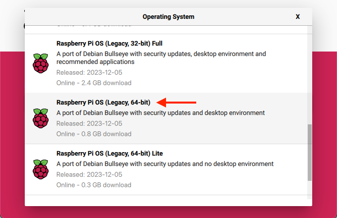
Base operating system image
The HAL requires Raspbian Bullseye 64-bit (i.e. it has not been tested with Buster). This can be installed using the Raspberry Pi Imager as described on the Raspberry Pi website. As of this writing, this OS is a little buried: after opening the “Operating System” menu, open “Raspberry Pi OS (other)” and scroll down to “Raspberry Pi OS (Legacy, 64-bit)”.
We recommend setting up the Pi with only basic peripherals (mouse, keyboard, monitor, and optionally wired network) connected — do not plug in any 454 hardware yet.
Common dependencies
There are a number of packages that will need to be installed to be able to compile and run the UI and HAL. Turn on the Pi, connect it to a network, and in a terminal, run the following:
# Initial setupsudo apt update
sudo apt upgrade
# Convenience packagessudo apt install htop tmux mosh git build-essential rsync python3-pip
# Needed to build libcamera-appssudo apt install -y libepoxy-dev libjpeg-dev libtiff5-dev
sudo apt install -y qtbase5-dev libqt5core5a libqt5gui5 libqt5widgets5
sudo apt install -y libavcodec-dev libavdevice-dev libavformat-dev libswresample-dev
sudo apt install -y cmake libboost-program-options-dev libdrm-dev libexif-dev
sudo apt install -y libboost-dev
sudo apt install -y libgnutls28-dev openssl libtiff5-dev
sudo apt install -y qtbase5-dev libqt5core5a libqt5gui5 libqt5widgets5
sudo apt install -y meson
sudo apt install -y libglib2.0-dev libgstreamer-plugins-base1.0-dev
sudo apt install -y libpng-dev
sudo pip3 install jinja2
sudo pip3 install pyyaml ply
sudo pip3 install --upgrade meson
# Pi-specific packages for hardware access# These *can* be installed on a regular aarch64 Debian Bullseye installation# to compile there instead, but they will have to be manually copied from the Pi reposudo apt install libcamera-dev libcamera0 libpigpio1 libpigpio-dev raspberrypi-kernel
# Python packages for UIsudo apt install python3-pyside2.* python3-pil python3-numpy python3-jsonschema
454 software
Now, it’s time to install the 454 software:
# Create required directoriesmkdir -p ~/454/output/manual
sudo mkdir -p /454/hal
# Clone, compile, and install the HALgit clone https://github.com/454bio/tirf-hal.git ~/454/hal-src
cd ~/454/hal-src
git submodule update --init --recursive
meson setup builddir
cd builddir
meson compile
rsync -avd ./ /454/hal/
# Clone the UIgit clone https://github.com/454bio/tirf-ui.git ~/454/ui
Configuration
To configure your specific hardware, first start by copying over the default configuration files:
The i2c_ variables here are consistent with the circuit described in the Electronics section, and the thermistor parameters are consistent with the recommended thermistor. If you selected a different thermistor, the appropriate values can be obtained from the datasheet.
If you are using the thermistor, your config must not also contain the 1-wire section below.
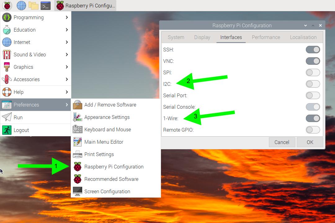
1-wire
First, you’ll need to enable the 1-Wire interface. In the “Interfaces” tab, turn on 1-Wire (labeled 3 above), then press OK. You will be prompted to reboot your Pi.
Then, edit /454/hardware_configuration_transformer.json to include the following:
If you are using the the 1-wire sensor, your config must not also contain the thermistor section above.
Camera
Vision Components camera
First, set up your Pi according to the Vision Components documentation.
After rebooting, it may be useful to proceed with normal setup first just to validate that the camera is working. To integrate with our software, set up external trigger in their driver software by editing /boot/config_vc-mipi-driver-bcm2835.txt:
Choose the config_vc-mipi-driver-bcm2835-raspi4B.txt platform
Choose the dtoverlay=vc-mipi-bcm2835-raspi3Bplus-cam0-imx183 overlay
Set the dtparam=cam0_sensor_mode_5 parameter
Leave the dtparam=cam0_io_config=8 parameter alone
Reboot
The VC camera has a quirk where it will use the external trigger to set the duration of the pulses only if the exposure time is 10 ms or less. At longer exposures, it will expose for the set duration and ignore the second pulse.
This is set in the HAL’s camera configuration at /454/vc_camera_config.json:
"exposure_time_us":10000,
Pi HQ camera
Support for the Pi HQ camera is included out of the box with Raspbian. To enable external trigger, append imx477.trigger_mode=2 to your /boot/cmdline.txt.
On a typical transformer, a complete /boot/cmdline.txt contains the following:
If you are using a standard color camera module (and not a debayered grayscale module), edit the HAL configuration at /454/libcamera_config.json to read:
"sensor_type":"imx477",
Filter wheel
The HAL configuration at /454/hardware_configuration_transformer.json has reasonable defaults for filter wheel position:
If images are out of focus between wavelengths, the positions may be adjusted:
Edit the configuration such that all of the positions are at zero (i.e. "red": 0, "orange": 0, ...).
Close the UI and restart the HAL (see below).
Use the live preview to image each wavelength and focus using the manual focus adjustment buttons. Take note of the values reported in the status bar (“Filter at [color name] position ([step number])”).
Add a desktop shortcut to the UI by copying 454-sequencing.desktop to ~/Desktop/454-sequencing.desktop
Usage
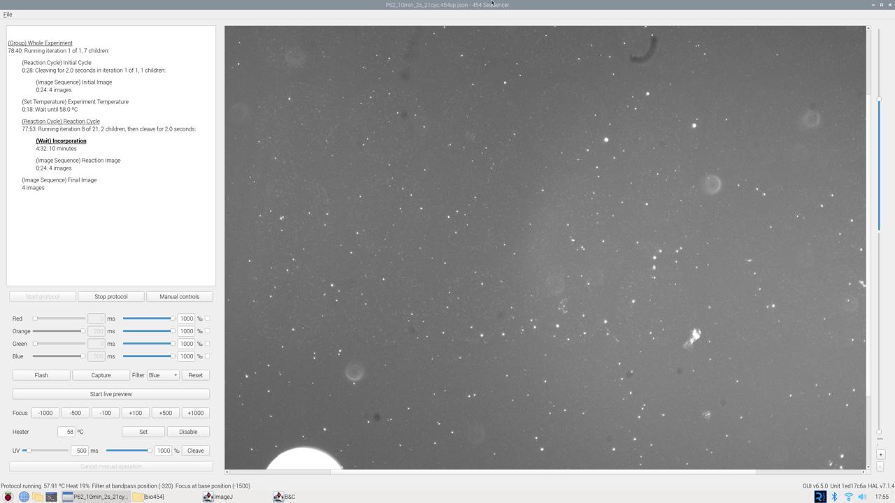
Manual image capture
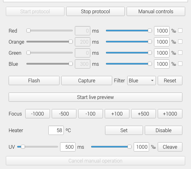
The manual controls allow realtime control of the sequencer hardware. To use the manual controls, open the UI and click the “Manual controls” button.
The top half configures visible light TIRF. After enabling any number of LEDs using the checkbox on the right, an exposure time in ms and intensity in ‰ (parts per 1000) can be set. These TIRF settings will be used when any of the following buttons are pushed:
“Flash”, which flashes the LEDs without capturing an image
“Capture”, which captures one image, saves it in ~/454/output/manual, and displays it in the preview
“Start live preview”, which continuously captures images and displays them in the preview.
The HAL automatically exposes the sensor just long enough for the configured TIRF.
If the filter is anything other than “Any filter”, the filter wheel will be moved to the set position before an image is captured.
The focus buttons nudge the base focus — the focus for all other colors will be adjusted by the same amount.
The “Heater” section will only be present if a temperature sensor is configured. The “Set” and “Disable” buttons respectively set the specified temperature or disable the heater entirely.
The “UV” section allows manual cleaving with the “Cleave”, and the time and intensity behave exactly like the visible light controls.
Automated data collection
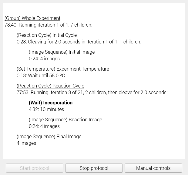
To collect data for sequencing automatically, open one of the preset sequencing protocols from the “File –> Open” dialog and then start it by pressing “Start protocol”. It will run until completion unless stopped with the “Stop protocol” button or a hardware error is detected.
If you would like to write your own automated sequencing protocol, you will have to do so manually as we have not yet implemented a protocol editor. Sequencing protocols are written in JSON, and can be validated with their JSON Schema specification .
Legacy code
The HAL used to be a fork of rpicam-apps (back when it was called libcamera-apps). This version of the code, along with all of its history, is available here .
A previous version of the instrument software was written in pure Python with GTK. While it only supports basic TIRF with the Pi camera (i.e. it lacks support for direct exposure control, the filter wheel, focus control, and live preview), it is available here for historical purposes only.
The Sequencing Reservoir is composed of a quartz sequencing substrate, a top reservoir piece, and bottom reservoir piece. The top and bottom pieces are made of polycarbonate with an over-molded TPE gasket that comes into contact with the quartz sequencing substrate. The bottom gasket allows the objective lens and camera sensor to capture images of sequencing in real-time as Lightning Terminators™ are incorporated on the top side of the sequencing substrate. The top piece of the sequencing reservoir forms the sequencing reaction vessel, and the top gasket seals the sequencing substrate to prevent leaks. The area bounded by the top gasket is covered in surface-bound forward and reverse primers. There is no exchange of fluid or cycling required for our truly one pot sequencing.
2.1 - Sequencing substrate preparation
Substrate preparation
Introduction
This protocol details materials and methods used to clean and activate quartz substrates for Sequencing Reservoirs.
The quartz substrates go through three stages of cleaning prior to activation: solvent, alkaline, and then an acid clean. Next, the clean slides are activated with piranha acid.
Commercially available MCP4 polymer is deposited on the surface of the activated substrate to provide a three dimensional layer of active NHS groups for oligonucleotide attachment.
Oligonucleotides with 5’ amine modifications are coupled to the slide surface. After blocking, washing, and drying the slides, they are ready to be assembled into Sequencing Reservoirs.
Assembled sequencing Reservoir with forward and reverse surface primers immobilized to sequencing substrate Created with BioRender.com and used with permission
Revision History
Document
Version Number
Date
Description of Change
Sequencing substrate preparation
V1.0
01/2024
Original document -KF
Materials and Equipment
Material or Reagent
Supplier
Order Information
Polished 10±0.1 x 10±0.1 x 0.5 mm Z-Cut Quartz
UQG Optics
custom part
Semiconductor grade 99.5% Isopropanol Alcohol
VWR
BDH2027
Semiconductor grade acetone
VWR
BDH2025
Semiconductor grade methanol
VWR
BDH2029
Reagent alcohol
VWR
BDH1156
deionized or 18.2MΩ water
various, in-house system ideal
n/a
Potassium Hydroxide
Spectrum Chemical
P1325
Hydrochloric acid (1N)
Sigma Aldrich
1506961000
Sulfuric acid (5M)
Sigma Aldrich
1.60315.1000
Hydrogen peroxide (30%)
BeanTown Chemical
219920
MCP4 Kit: 5x Coat on Coating Solution, MCP4 Polymer Concentrate, Spot on Spotting Solution, 2x Block on Blocking Solution
Handle organic solvents, strong bases, and acids with extreme caution, prioritizing safety at all times. Utilize appropriate personal protective equipment, including goggles and gloves, maintain workspaces well-ventilated or equipped with fume hoods, and strictly adhere to established protocols for storage, handling, and disposal.
NHS esters in aqueous solution will undergo hydrolysis. Do not allow MCP4 working solution to sit unused once polymer is added. Ensure MCP4 coated slides are washed aggressively after coating to remove uncoupled polymer without over exposing to water.
Procedure
1. Clean Z-Cut Quartz Slides
Solvent clean
Submerge slides vertically in a bath of semiconductor grade acetone
Sonicate 5 minutes
Transfer slides to a bath of semiconductor grade isopropyl alcohol
Sonicate 5 minutes
Transfer slides to a bath of methanol
Sonicate 5 minutes
Alkaline clean
Transfer slides to a bath of 10% potassium hydroxide in methanol (% w/v)
Sonicate 20 minutes at 50º C
Transfer slides to a bath of reagent alcohol
Sonicate for 20 minutes at 50º C
Repeat steps 1.2.1 through 1.2.2 for a total of two potassium hydroxide and two reagent alcohol washes
Transfer slides to a water bath
Sonicate for 5 minutes
Transfer slides to a new water bath
Repeat steps 1.2.4 through 1.2.5 for a total of 3 washes with sonication
Transfer slides to a methanol bath
Sonicate for 5 minutes
Acid clean
Transfer slides into a fresh bath containing a solution of 50% hydrochloric acid in methanol
Sonicate for 30 minutes at 60º C
Transfer slides to a water bath
Sonicate for 5 min.
Repeat step 1.3.2 two more times for a total of three washes, using a fresh water bath for each wash
Dry slides thoroughly with filtered compressed nitrogen
Any residual moisture will dry onto slide, TIRF system is very sensitive to any residue, debris, or dried material on slide surface
Store until ready to proceed to acid cleaning step
Safe stopping point
Slides can be stored dry in desiccator for many weeks.
2. Piranha activate clean slides
Transfer slides to a bath containing piranha acid
Prepare piranha acid by combining 1 volume 30% hydrogen peroxide to 3 volumes of 5 M sulfuric acid
Sonicate for 60 min at 60º C.
Transfer slides into a water bath
Sonicate for 5 min.
Repeat step 2.2 four times for a total of 5 water washes with sonication, using a fresh water bath each time
Ensure all traces of piranha acid are removed
Dry slides thoroughly with filtered compressed nitrogen
Any residual moisture will dry onto slide, TIRF system is very sensitive to any residue, debris, or dried material on slide surface
Keep going
Proceed immediately to MCP4 Polymer Deposition
3. MCP4 polymer deposition
Prepare MCP4 working solution by combining the following reagents:
Note: DO NOT add polymer to solution until slides are ready for incubation
Incubate activated slides in MCP4 Working Solution for 30 minutes
Slides can be submerged or assembled in fixtures that allow for a pool of working solution to cover a desired area
After incubation, slides need to be aggressively washed in deionized water
Submerge in running 5 minutes, or submerge in multiple passive baths of deionized water. If slides are assembled in fixtures, recommend disassembling and washing an addition 1-3 minutes vertically in running water.
Dry slides thoroughly with filtered compressed nitrogen
Any residual moisture will dry onto slide, TIRF system is very sensitive to any residue, debris, or dried material on slide surface
Cure dry slides at 80º C under high vacuum
Keep going
Proceed immediately to oligo immobilization
4. Oligo immobilization
Prepare a 250 uM each solution of forward and reverse surface primers in nuclease free water
Concentrations can be optimized experimentally
Determine ideal spotting conditions for your DNA microarray printer
Surface primer solution can be diluted 1:1 with Spot on Spotting Solution when ready to spot primers onto surface
Incubate slides overnight
Keep going
Proceed to slide blocking, washing, and drying
5. Blocking, washing, drying
Prepare 1x Block on Blocking solution by diluting stock 1:1 in nuclease free water
Fill vertical reaction chambers with 270-300 uL of solution
Transfer slides from overnight incubation into the pre-filled reaction chamber
Incubate at 50 C for 30 minutes
Place slides vertically in a deionized water bath
Incubate 5 min in running water
Transfer slides to a 2x SSC + 0.1% SDS solution and incubate 10 minutes with enough shaking to agitate the solution without dislodging slides
Place slides vertically in a deionized water bath
Incubate 5 min in running water
Dry slides thoroughly with filtered compressed nitrogen
Any residual moisture will dry onto slide, TIRF system is very sensitive to any residue, debris, or dried material on slide surface
Safe stopping point
Slides can be stored dry in desiccator or used directly for assembling sequencing reservoir.
The assembly station is constructed on a solid heavy base to prevent movement during assembly. The design above is just a typical example and requires 4 appropriately spaced M5 tapped holes.
Procedure
Place the Reservoir Assembly Jig Vacuum base on the heavy base and secure with two M5 screws (91292A192).
Place the 3D printed Reservoir Centering Fixture on top of the Vacuum base and secure it with two M5 screws (91292A193).
Screw the push-to-connect elbow fitting (5779K652) into the back port (1/8 NPT).
Hook up the venturi pump with and appropriately valved air valve and place the O-ring in the center of the Vacuum Jig base (9262K421).
The system is ready to be used for the assembly of the reservoirs.
2.3 - Sequencing reservoir assembly
Reservoir Assembly
Introduction
This protocol details materials and methods to assemble Sequencing Reservoirs. The reservoir is composed of three major parts: reservoir Top, reservoir Bottom, and sealed in between the two, the sequencing substrate coated in immobilized surface primers.
A vacuum fixture is used to hold the reservoir bottom in place as the sequencing substrate is aligned on top of the gasket of the reservoir bottom. Once well aligned, the vacuum is turned on and will hold the slide firmly to the gasket. The gasketed surface of the reservoir top is then placed on top of the slide, and force is applied to lock the reservoir top legs into the reservoir bottom. Looking down into the reservoir through the top reveals about 20 mm² of the sequencing substrate. The top surface of the substrate is covered in immobilized surface primers and ready for sequencing library hybridization.
A press is used to compress the whole assembled sequencing reservoir to help ensure there are no leaks during subsequent steps.
Sequencing substrates and reservoir tops and bottoms should remain particle free. Components should be stored in clean air tight containers when not in use. For manipulation it is recommended to work in a clean room and/or within a laminar flow hood. All materials for reservoir assembly should be placed within clean space before starting procedure.
Procedure
1. Assemble Reservoir
Place reservoir bottom onto the vacuum block with the TPU gasket facing up and the elevated legs in the top left and bottom right corners
Using tweezers, carefully place the slide onto the bottom part of the reservoir with the oligo coated side facing up
Use tweezers to gently manipulate slide so it is centered over the reservoir bottom
Turn the vacuum on so the slide and bottom reservoir are help in place for next steps. Ensure slide is still centered over reservoir bottom
Screw on a cap to the reservoir top
Hold the reservoir top over the slide and reservoir bottom so the longer legs are positioned over the longer leg inserts of the reservoir bottom
Longer pieces of both parts should be at the top left and bottom right corners
Once properly positioned, carefully lower reservoir top onto reservoir bottom so the legs are resting on the leg inserts
Depress forcefully to finish assembling the reservoir
Listen for two audible “clicks” as the reservoir top is fitted into the reservoir bottom
2. Check assembly
Turn off vacuum holding reservoir in place and remove assembled reservoir
Inspect edges of glass slide to ensure it is still well centered between top and bottom pieces and there are no corners or sides protruding
Inspect gasket to slide contact of top and bottom pieces ensures there are no gaps between glass and gaskets
3. Press assembled reservoir to prevent leaking
Place reservoir cap-down in reservoir press fixture
Turn on press and wait 5 seconds
Turn off press and remove reservoir
Label reservoir for your experiment
Safe stopping point
Assembled reservoirs can be stored dry at room temperature for weeks to months
2.4 - Linear DISCS preparation
DISCS Preparation
Introduction
454’s One Pot Sequencing relies on the 365nm UV TIRF to deblock Lightning Terminator dye linked terminator groups. Stray UV light also deblocks the free Lightning Terminators™ in the bulk solution. The resulting deprotected dNTP competes with LTs during incorporation by Therminator and causes significant leading.
We have developed DISCS (Dark Base In-Situ Cleanup System): which includes Bst 3.0 DNA polymerase from NEB and a set of duplex oligos to quickly consume the deblocked dNTP (dark bases). DISCS is crucial for the success of One Pot Sequencing.
This protocol describes the procedure to prepare linear DISCS for one pot sequencing.
Revision History
Document
Version Number
Date
Description of Change
DISCS
V1.0
Jan 2024
original JW
Materials and Equipment
Item
Vendor
Cat. No
ThermoPol Buffer, 10x
NEB
B9004S
IDTE, pH 8.0
IDT
11-05-01-09
A_DISC_F
IDT
AAAAAACTATGACCGTGATTAGGCCAAGCTCGCACG
A_DISC_R
IDT
AAAAAACGTGCGAGCTTGGCCTAATCACGGTCATAG
C_DISC_F
IDT
AAACCCCTATGACCGTGATTAGGCCAAGCTCGCACG
C_DISC_R
IDT
AAACCCCGTGCGAGCTTGGCCTAATCACGGTCATAG
G_DISC_F
IDT
AAAGGGCTATGACCGTGATTAGGCCAAGCTCGCACG
G_DISC_R
IDT
AAAGGGCGTGCGAGCTTGGCCTAATCACGGTCATAG
T_DISC_F
IDT
AAATTTCTATGACCGTGATTAGGCCAAGCTCGCACG
T_DISC_R
IDT
AAATTTCGTGCGAGCTTGGCCTAATCACGGTCATAG
Water, nuclease free
IDT
11-05-01-04
Thermal cycler
various
n/a
Pipettes and tips (200 uL, 20 uL, 2 uL)
various
n/a
Procedure
Resuspend fresh oligo pellets from IDT with IDTE to 200 uM stock concentration.
Bring 10X ThermoPol buffer, 100 mM MgSO₄ and DTT from the -20°C freezer to room temperature for 30 minutes to thaw
Bring all other chemicals to a clean area.
Use a clean container (for example, a glass beaker) to prepare the buffer.
Add the required volume of each liquid component to the container.
Record the lot information and the quantity added to the worksheet.
Make sure the DTT bottle reaches room temperature and there is no condensation on the bottle before opening the cap.
Return DTT to the freezer once finished.
After all chemicals are added, fill the container with the nuclease free water to 1 mL less than the total volume.
Stir slowly to mix.
The pH should be around 8.3-8.4. Adjust pH to 8.8 at 25°C with 1 M NaOH.
Add nuclease free water to bring mixture up to total volume.
Filter the buffer with 0.2 µm filter.
Aliquot 1.5 mL buffer to 2.0 mL clean centrifuge tubes for storage at -20°
3 - Start sequencing
Sequencing guide
With the LED-TIRF Transformer built and the Sequencing Reservoir consumable assembled, you are ready to begin sequencing!
The first step to sequencing is to prepare a sequencing library. This entails taking your DNA sequence of interest and adding specific known DNA sequences to it. This process allows you to sequence your unknown sequence of interest on the Transformer.
The library molecules will all contain the complement to the surface-bound forward primer on the sequencing substrate. This allows each molecule to hybridize to the sequencing substrate so a polymerase can initiate surface amplified cluster generation.
Library molecules also contain the surface-bound reverse primer sequence. As forward strands are generated using the library molecules as template, the complement of the surface-bound reverse primer is polymerized so the surface-bound reverse primers can anneal and a polymerase can extend reverse strands. As more copies of forward and reverse strands are produced branching off of the surface and the growing cluster, the cluster becomes hyperbranched.
Another important library element is the site for the sequencing primer. The hyperbranched surface amplified clusters will contain a primer binding site just upstream of the DNA sequence of interest. When you’re ready to sequence, the sequencing primer will anneal to this site. The first base extended from this sequencing primer will be the first base of your DNA of interest.
3.1 - Library preparation
Library preparation
Introduction
This protocol details methods to prepare circular single stranded DNA library using 5’ phosphorylated synthetic linear ssDNA as starting material (synthetic library). Oligonucleotides can be ordered from IDT, resuspended, and used directly in CircLigase reaction to produce synthetic library.
Library insert size is critical to success using the TIRF Transformer system and rolling circle surface amplification (RCA). Template copy number in sequencing clusters is highly dependent on insert length. Longer insert translates to lower copy number in RCA generated sequencing clusters, and consequently, reduced signal upon Lightning Terminator incorporation.
Revision history
Document
Version number
Date
Description of change
Library preparation
v1.0
12/2023
Original document -KF
Materials and equipment
Material or Reagent
Vendor
Order Information
Link
Synthetic Library Molecule: /5Phos/AATGATACGGCGACCACCGAGATCTACACTCTTTCCCTACACGACGCTCTTCCGATCT< insert >ATCTCGTATGCCGTCTTCTGCTTG *where < insert > is your DNA sequence of interest. for getting your system going, we recomend at least 4 16-nt templates with high diversity at each position
Various- Qubit ssDNA kit, for example. Not needed for A260 quantitation
n/a
n/a
Equipment
Vendor
Thermocycler
Various
Vortex
Various
Mini centrifuge
Various
PCR tube magnet stand
Various
UV/Vis system or Fluorometer for DNA quantitation
Various
P-1000 pipette and filtered tips
Various
P-200 pipette and filtered tips
Various
Optional: P-20 and/or P-10 pipette and filtered tips
Various
1.5 mL nuclease free tubes
Various
Nuclease free PCR tubes
Various
Notes before starting
Consider insert length when designing synthetic library molecules as longer inserts will compromise sequencing quality (lower signal per cluster). We have achieved good results with 16 nt inserts.
CircLigase efficiency decreases with templates greater than 100 nt. We have achieved good results with templates from 85 to about 300 nt.
Exonuclease treated CircLigase products are cleaned up using Ampure XP beads. Alternative purification methods suitable for single stranded circular DNA can be substituted.
Procedure
1. Prepare materials
Resuspend or dilute synthetic templates to 100 µM in nuclease free H₂O
Optional: prepare aliquots to minimize freeze-thaw cycles
Optional: Pool synthetic templates to reduce number of circularization reactions
Combine equal volumes of each 100 µM template (minimum of 4 µL required per reaction for next steps)
2. Circularization of synthetic templates
Prepare one new, clean PCR tube per circularization reaction
One reaction should produce ample material for hundreds of sequencing reactions
Templates can be pooled or circularized individually
Load the following program on a thermocycler:
Temperature
Time
60 ºC
16 hours
80 ºC
10 minutes
Prepare CircLigase Reaction Mix by combining the following components in order on ice using the tubes prepared in step 2.1:
Reagent
Volume for 1 reaction
Final concentration
Nuclease free water
13 µL
Circligase buffer, 10x
2 µL
1x
MnCl₂, 50 mM
1 µL
2.5 mM
ATP, 1 mM
1 µL
50 µM
Synthetic template(s), 100 µM total
2 µL
10 µM total
CircLigase I
1 µL
5 U/µL
Total volume
20 µL
Vortex and spin down reaction mix
Load tubes onto thermocycler and run the program loaded in step 2.2
3. Exonuclease cleanup
Optional: Prepare linear controls with and without exonuclease treatment:
Transfer 18 µL of 1x CutSmart buffer or 1x CircLigase buffer into two tubes, one labeled -exo and one labeled +exo
Add 2 µL of the 100 µM linear synthetic templates used in circularization reaction to each of the two tubes
Prepare exonuclease mixture:
Combine 1 µL Exonuclease I and 1 µL Exonuclease III in a tube per reaction on ice
Note: exonuclease III is only needed for templates with secondary structure and/or contaminating double stranded DNA
Vortex and spin down
Add two µL of exonuclease mixture to each CircLigase reaction and +exo linear control tube on ice. Pipette up and down to rinse tip after dispensing mixture
Vortex each reaction mix and spin down
Load the following program on a thermocycler:
Temperature
Time
37 ºC
40 minutes
80 ºC
20 minutes
4 ºC
forever
Load samples on thermocycler and run the program loaded in step 3.4
4. Library purification: 1.2x ampure cleanup
Prepare materials:
Allow Ampure XP beads to come to room temperature for 15-30 minutes
Prepare a fresh 80% absolute ethanol solution by combining 200 µL molecular biology grade absolute ethanol with 50 µL of nuclease free water per sample
Vortex Ampure XP beads aggressively to ensure beads are resuspended in a homogenous solution
Label one clean, new PCR tube per sample for the final elution step
Dispense 26 µL well mixed Ampure XP beads into each sample, pipetting up and down at least ten times to mix beads with sample
Pipette slowly and carefully, bead mixture is viscous
Incubate samples with beads on benchtop for 5 minutes
After 5 minute incubation, place samples on magnet stand and allow beads to pellet for 5 minutes
Using a p-100 or p-200 pipette, remove supernatant from each sample tube while on magnet stand, leaving behind beads pelleted to tube wall
Ethanol wash:
Dispense 100 µL 80% ethanol solution into each sample tube
Rotate tube 180º in magnet stand
Once beads have pelleted on the tube wall again, carefully remove supernatant
Repeat ethanol wash (step 4.6) again for a total of two washes
Dry beads:
After removing supernatant from the second wash, spin tubes down and replace on magnet stand with caps open
Using a p-10 pipette, remove any excess ethanol solution
Leave caps open and allow beads to dry for 3-5 minutes
Beads are sufficiently dry when pellet goes from a shiny to matte finish. Beads are overly dry if bead pellet begins to crack
Elute DNA
Once beads are dry and any ethanol has evaporated off, dispense 30 µL of nuclease free H₂O or low TE buffer onto bead pellets
Vortex each sample to ensure beads are in solution and not stuck to sides of tube
Quickly spin down to bring liquid to bottom of tube without pelleting beads
Incubate samples on benchtop (not magent) for 2 minutes
Replace samples on magnet and allow beads to pellet for 2 minutes
Carefully transfer supernatant containing DNA into the new, clean tubes prepared in step 4.1.4.
Beads can be discarded
5. Library quantitation and quality check
Determine library concentration in ng/µL
Libraries can be quantitated using fluorometric (Qubit ssDNA kit or other similar) or A260 (Nanodrop or similar)
Using library concentration and known size of synthetic templates, determine molarity (nM)
The +exo control tube should not have any DNA
6. Libraries can be aliquoted and stored at -20º C
Libraries can be diluted to 1 nM before aliquoting for long term storage
3.2 - Surface amplification
Surface amplification
Introduction
This protocol describes the materials and methods to generate surface amplified sequencing clusters on a reservoir.
Circular single stranded library hybridizes to surface immobilized forward primers. These primers initiate rolling circle amplification (RCA) to generate sequencing clusters. The forward strands produced will contain sequences which will anneal to the surface immobilized reverse primers. These primers are extended to produce reverse strands. Hyperbranched clusters are produced by forward and reverse RCA products annealing to the surface primers and initiating polymerization of more forward and reverse products.
Once hyperbranched clusters are generated by RCA, Thermolabile USER II is used to cleave the reverse strands from the surface. After denaturing and washing, the sequencing reservoir surface contains thousands of forward strand RCA clusters.
Since the TIRF system is highly sensitive to any incorporation at the sequencing reservoir surface, TdT is used to terminate all remaining 3’ ends after USER treatment. After a last set of denature and wash steps, the surface amplified clusters on the reservoir surface are ready to be sequenced on the LED-TIRF Transformer.
Hybridize library to sequencing substrate
Generate surface amplified sequencing clusters using Rolling Circle Amplification
Optimal circular library hybridization concentration is critical to achieving a high density of sequencing clusters without compromising monoclonality. We have achieved good results hybridizing clusters at concentrations of 0.15-0.4 pM, but ideal concentrations should be determined empirically.
Sodium hydroxide dilutions should be made fresh for same day use.
Procedure
1. Prepare reservoir for hybridization
Dispense 100 µL nuclease free (NF) H₂O into a new reservoir, being careful not to contact glass surface at bottom of reservoir
Aspirate and discard the liquid from the reservoir with P-100 or P-200 pipette by tilting the reservoir opening towards you and carefully placing the tip of the pipette at the lowest edge of the reservoir
2. Hybridize library
Dilute library to loading concentration
Library should be at 0.15 - 0.4 pM in 2x SSC + 0.1% Triton X 100 (SSCT)
Ensure there is at least 100 µL of diluted library per reservoir
Dispense 100 µL diluted library into reservoir
Incubate reservoir at 65º C for 4 minutes, 40º C for 44 minutes, and then room temperature for 4 minutes
After final 4 minute room temperature incubation, remove and discard 100 µL solution from reservoir
Dispense 50 µL of 1x RCA Buffer into reservoir
Safe stopping point
Proceed to cluster generation within 1 day. Reservoir can be stored at room temperature.
3. Cluster generation
Make Phi29XT Reaction Mix using the table below, adding each component in order:
Reagent
Volume for 1 reservoir
Final concentration
Nuclease free water
60 µL
Phi29-XT Reaction Buffer, 5x
20 µL
1x
dNTP Solution Mix, 10 mM
10 µL
1 mM
Phi29XT Polymerase, 10x
10 µL
1x
Total volume
100 µL
Vortex and spin down reaction mix, keep on ice
Remove 1x RCA buffer from sequencing reservoir by tilting reservoir towards you and aspirating at the lowest edge of the reservoir with a p-100 or p-200 pipette
Dispense 50 µL of the Phi29XT Reaction Mix into the reservoir
Ensure liquid is at bottom of reservoir
Store remaining reaction mix at 4º C for a reaction refresh
Incubate reservoir at 42º C for 30 minutes
Refresh Phi29XT Reaction Mix:
After 30 minutes, remove 20 µL of Phi29XT Reaction Mix from reservoir
Dispense the 50 µL of Phi29XT Reaction Mix remaining from step 3.3.2 into the reservoir and gently swirl
Ensure all liquid is at bottom of reservoir and incubate at 42º C for an additional 2 hours
After 2 hour incubation, proceed directly to step 4
4. Cleave reverse strands
Begin incubating the reservoir with Phi29XT Reaction Mix at 37º C
Dispense 2 µL of Thermolabile USER II enzyme into the reaction mix, pipetteing up and down to ensure full volume is dispensed
Tilt the reservoir towards you and use a P-100 or P-200 pipette set to 50 µL to gently and carefully mix the liquid without contacting the bottom surface of reservoir
Incubate the reservoir at 37º C for 30 minutes
4.5. After 30 minutes, remove the reaction mix
Denature reverse strands
Dispense 100 µL of 100 mM NaOH into reservoir
Incubate 3 minutes at room temperature
Remove NaOH from reservoir
Rinse reservoir:
Dispense 200 µL NF H₂O into reservoir
Pipette up and down 3 times to agitate the surface of the reservoir with the liquid
Remove NF H₂O
Repeat step 4.6.3 two times for a total of three rinses
Dispense 100 µL of 2x SSC + 0.1% Triton X 100 into reservoir
Safe stopping point
Reservoir can be stored at room temperature.
5. Block surface
Albumin blocking:
Prepare albumin blocking solution using the table below:
Reagent
Volume for 1 reservoir
Final concentration
Nuclease free water
42.5 µL
Terminal Transferase Buffer, 10x
5 µL
1x
Recombinant Albumin, 20 mg/mL
2.5 µL
1.12 mg/mL
Total volume
50 µL
Vortex and spin down mixture
Remove liquid from reservoir
Dispense 50 µL of albumin blocking solution into reservoir
Incubate 10 minutes at room temperature
3’ end blocking:
Prepare terminal transferase (TdT) Reaction Mixture using table below:
Reagent
Volume for 1 reservoir
Final concentration
Nuclease free water
35 µL
Terminal Transferase Buffer, 10x
5 µL
1x
CoCl₂, 10x
5 µL
1x
Dideoxynucleotide Solution, 2.5 mM (0.625 mM each ddATP, ddCTP, ddGTP, ddTTP)
4 µL
0.2 mM
Terminal Transferase, 20,000 U/mL
1 µL
400 U/mL
Total volume
50 µL
Vortex and spin down mixture
Remove albumin blocking solution from reservoir
Dispense 50 µL TdT Reaction Mixture into reservoir
Ensure all liquid is at bottom of reservoir
Incubate at 37º C for 30 minutes
Denature protein and rinse reservoir
Remove reaction mix from reservoir
Dispense 100 µL of 100 mM NaOH into reservoir
Incubate 3 minutes at room temperature
Remove NaOH from reservoir
Rinse reservoir:
Dispense 200 µL NF H₂O into reservoir
Pipette up and down 3 times to agitate the surface of the reservoir with the liquid
Remove NF H₂O
Repeat step 5.3.4 two times for a total of three rinses
Dispense 100 µL of 2x SSC + 0.1% Triton X 100 into reservoir
Safe stopping point
Reservoir can be stored at room temperature, or proceed to sequencing protocol.
3.3 - Sequencing
Sequencing starts now
Introduction
Traditional Sequencing By Synthesis technologies typically involve separate incorporation, washing, imaging, and cleavage steps with continuous feeding of multiple buffers. 454 Bio’s One Pot sequencing on the LED-TIRF based Transformer only needs one solution without any fluid exchange for imaging, washing, or cleaving steps.
One Pot Sequencing on the LED-TIRF Transformer takes place at a constant temperature of 58 C. A cycle of sequencing consists of a 10 minute incubation to allow for Lightning Terminator incorporation. Next, the 4 visible wavelength LEDs are pulsed to excite each Lightning Terminator. Images are captured in real time. After images are taken to record which base was incorporated, the Lightning Terminators™ are photocleaved by the UV LED. The linked dyes on incorporated Lightning Terminators™ are cleaved and diffuse away, allowing for the next base incorporation. This process is repeated for each cycle of sequencing.
This protocol describes the procedure to set up One Pot Sequencing on the LED-TIRF Transformer.
Lightning Terminators™ need to be carefully handled and only exposed to shorter than 500 nm light. Care should be taken to protect Lightning Terminators™ from photobleaching and from photocleaving due to exposure to light.
Enter the required information based on your experiment plan.
Retrieve OPB buffer, Seq Primer, LTMix, DISCS from -20°C freezer and thaw them by leaving them on the bench for 30 minutes at room temperature.
Pre-heat Transformer to 65°C.
Seq Primer Hybridization:
Prepare sequencing primer hybridization solution following the worksheet.
Add 120 µL hybridization solution into the sequencing reservoir.
Load the reservoir onto the pre-heated 454 Bio Transformer.
Incubate reservoir at 65°C for 10 minutes.
Bring the reservoir to the bench and incubate at room temperature for 10 minutes
Set Transformer temperature to 58°C for sequencing.
Rinse reservoir with 120 µL OPB once.
Therminator Preloading:
This step can be skipped if circular DISCS or RNA DISCS is used.
Prepare Therminator solution following the worksheet.
Add 60 µL Therminator solution into the reservoir.
Incubate for 3 minutes at room temperature.
Rinse the reservoir with 120 µL OPB once.
Ensure Transformer temperature has reached 58° C
Prepare sequencing solution using the worksheet.
Mix the solution thoroughly by vortexing and spinning. Tap the tube with fingers to remove any bubbles.
Carefully add the solution to reservoir avoiding any bubbles.
Load the reservoir on the Transformer.
Set a timer for 10 minutes for the first cycle incorporation.
After 10 minutes, manually adjust the focus for each wavelength:
In the manual controls, select a filter and pulse time and then start the preview.
Use the focus adjustment buttons to bring the clusters in focus.
Stop the preview.
Verify that all other wavelengths are in focus by repeating steps 13.1 and 13.3 for each wavelength. It should not be necessary to refocus any wavelength.
Repeat steps 13.1 to 13.3 for each wavelength After four wavelengths’ cluster images are all in focus, switch the focus pin to auto position.
Start the protocol and one pot sequencing will automatically finish all desired cycles.
4 - Analysis software
This section outlines the data analysis pipeline for the “One pot” Lightning Terminators™ (LT)
Introduction
This section outlines the data analysis pipeline for the “One pot” Lightning Terminators™ (LT) sequencing process. During each sequencing cycle, the Transformer MK3 prototype sequentially activates different LED light excitations. This process captures and stores four monochrome raw images corresponding to each fluorescent dye-labeled LT (Atto647-LT-dT, AF594-LT-dA, AF532-LT-dC, AF488-LT-dG). The total number of images generated is equal to the number of cycles multiplied by four, representing the four distinct color channels.
Correction Procedures: magnification correction, background normalization across different color channels, light illumination uniformity correction, cycle to cycle image registration (translation, rotation)
Defect Removal: Processes the well-registered images to eliminate surface scattering defects.
ROI Detection and Intensity Extraction: Utilizes the first cycle image set to identify each DNA cluster’s centroid (Region of Interest, ROI) and extracts intensity values at each cycle for subsequent analysis.
Below is a set of processed raw images demonstrating these steps.
Color Transformation
This section introduces our newly-developed algorithm designed to assess the ‘color purity level’ of each cluster in a given cycle.
The algorithm evaluates the unique fluorescence signature of each dye and considers the optical cross-talk among the four color channels. In the initial cycle, images are presumed to be nearly ‘pure’, typically exhibiting only a single dye per cluster spot. However, in subsequent cycles, a mixture of dyes may appear within each cluster spot towards the end of the cycle, a result of dephasing. Our color transformation algorithm adeptly quantifies the proportion of each dye present at the conclusion of each cycle.
Below shows a typical example of how a certain cluster’s “color purity” (each color represents base A, C, G, T) changes from cycle 1 to cycle 5.
Dephasing Correction and Basecalling
Dephasing is a significant issue in our cyclic reversible terminations. It refers to the loss of synchrony in the signal from a cluster of DNA molecules being sequenced simultaneously. In our one pot sequencing, it’s expected that all DNA strands in a specific cluster will incorporate the same nucleotide at each cycle of the sequencing process. However, due to various factors like insufficient UV cleavage, Polymerase fall off, some strands may fail to incorporate a nucleotide at a given cycle (a ’lag’) or some factors like “darkbase” (non-terminated LTs) generation, some strands incorporate more than one (a ’lead or carry forward’). This results in a loss of synchrony or “phasing” over time.
Our dephasing correction algorithm uses computational methods to model the expected signal from the color transformed clusters, detect and minimize the deviations, and apply corrections to the sequencing readouts to improve the accuracy of the base call.
Functionality:
ClusterSeqIP_v2.py preprocesses raw images from a sequencing run and outputs processed images into a designated folder, preparing them for color transformation. Key operations include image renaming, filtering, binning, background normalization, magnification correction, image registration, cropping, and illumination correction.
Execution Instructions:
Ensure Fiji.app is downloaded and installed.
Verify that PyImageJ, OpenJDK 11, and Maven are properly installed.
In the script, set JAVA_HOME to the correct directory, for example:
Note: Python will call Fiji to perform image registration. This requires users to manually adjust the cropping rectangle to the center and set the threshold to approximately 0.08.
Output:
2_preprocess: Stores preprocessed images for debugging and manual registration.
2_Regis: Contains registered images for end-users to visualize and check registration quality.
2_processed_final: Holds the final processed images for the next step of color transformation. Pass this directory to DoG_v1.py once you confirm all images are properly processed.
DoG_v1.py
Functionality:
DoG_v1.py processes the final image files to perform cluster spot detection using the Difference of Gaussians (DoG) method. It extracts intensity values from the processed images, applies a Chastity filter, and utilizes several other distance/intensity-based filters to eliminate unwanted spots. Finally, the script identifies dictionaries for all four base colors and outputs the intensities, cluster centroids, and dictionary as a CSV file, which is essential for the subsequent color transformation process.
Execution Instructions:
Confirm that the folder 2_processed_final exists and contains all properly processed images. The total number of images should be a multiple of four, corresponding to the four fluorescent channels.
Execute the script in the terminal, specifying the path to your 2_processed_final image folder:
Output:
Binary_Mask: Stores the binary mask of auto-detected cluster spots using the first cycle of the sequencing run (images 00001-00004.tif), and the final mask used for intensity extraction after all filtering processes (Mask_afterChastity.tif).
Cluster_intensities.csv: This CSV file contains the spot ID, the centroid of each spot, the Gaussian integrated intensity values of each spot across all channels and cycles of sequencing, and the auto-detected cluster medians chosen as a dictionary for A, C, G, T, and global background intensity.
Color Transformation:
color_transform.py
Functionality:
color_transform.py processes the extracted intensity values of each cluster spot based on the selected dictionaries to solve the transformation matrix, which eventually transforms the intensity into each fluorescence channel’s (or in other words, each A, C, G, T bases’) color purity as its name indicated.
color_transform.py processes the intensity values extracted from each cluster spot. It solves the transformation matrix, based on the provided dictionaries, effectively converting the intensity data into color purity levels for each fluorescence channel. In essence, it translates intensity values with optical cross-talk into the respective color purities of the A, C, G, T bases.
Execution Instructions:
Ensure the file Cluster_intensities.csv is present and accessible.
Execute the script in the terminal, specifying the path to your Cluster_intensities.csv:
Output:
color_transformed_spots.csv: This CSV file contains the proportion of each color (A, C, G, T) for each spot across different sequencing cycles. It is a crucial file for subsequent steps in dephasing correction and base calling.
Dephasing Correction and Basecalling:
default_analysis.sh
Functionality:default_analysis.sh is a Bash shell script that executes a series of commands to invoke various Python files. These files perform crucial tasks such as dephasing correction (addressing incomplete extension, carry-forward, and signal decay), base calling, mapping sequences to ground truth, evaluating mapping quality scores, and generating an HTML-based run report for end-users to visualize sequencing results.
Execution Instructions:
Ensure the file color_transformed_spots.csv is present and accessible.
For first-time users, open default_analysis.sh, review, and modify the directory paths as needed.
Execute the script in the terminal, and make sure the color_transformed_spots.csv is under the same directory as your default_analysis.sh
bash ...your directory/default_analysis.sh your_output_name fast
Please note that the “fast” version will predetermine fixed parameters of the incomplete extension, carry-forward, and signal decay, and the standard version without “fast” will perform grid search and error function fitting for each individual cluster.
Output:
Some of the key files include
your_output_name.html
your_output_name.fastq
your_output_name.txt.filtered
Please refer to our blog post for more details of how to run the entire data analysis pipeline for an exemplary data set.
5 - License
This documentation is licensed under CC BY-SA 4.0.
The licenses in our GitHub repositories solely authorize use of the software, hardware models, and other content provided in the repositories and provide no other license.
Usage of Lightning Terminators™️ is governed by a separate license provided upon purchase.